
Design method for wide-range high-precision microwave distance measurement radar system

A technology of microwave distance measurement and radar system, which is applied in the direction of radio wave measurement system, measurement device, radio wave reflection/reradiation, etc., can solve the problems of difficult engineering implementation, affecting the measurement distance, low modulation bandwidth, etc., and achieve improvement Integration and reliability, simplified software processing flow, and reduced design difficulty

Active Publication Date: 2014-07-30
XIAN INSTITUE OF SPACE RADIO TECH
View PDF3 Cites 9 Cited by
  • Summary
  • Abstract
  • Description
  • Claims
  • Application Information

AI Technical Summary

Problems solved by technology

On the one hand, the narrow pulse measurement technology has a low duty cycle due to the narrow transmission pulse, which affects the measurement distance; on the other hand, due to the narrow pulse, its modulation bandwidth is low, so the measurement accuracy is low
[0007] According to the ranging requirements of the landing process, the short-range measurement is up to 15m, and the measurement accuracy is 0.4m below 120m. After analysis, the measurement range and measurement accuracy must be satisfied at the same time. The ranging pulse width must be less than 100ns, and the signal bandwidth must be greater than 100M, that is, the frequency modulation slope must be greater than 1*10 15 Hz / s, which is difficult to achieve in engineering
[0008] Narrow pulse short-distance measurement can synthetically synthesize large-bandwidth signals through frequency stepping, but its processing method is quite different from that of ordinary pulse ranging, and it is difficult to realize the unified design of long-distance and short-distance

Method used


Image

  • Design method for wide-range high-precision microwave distance measurement radar system
  • Design method for wide-range high-precision microwave distance measurement radar system
  • Design method for wide-range high-precision microwave distance measurement radar system

Examples


Embodiment Construction

[0040] Further illustrate working principle and working process of the present invention below in conjunction with accompanying drawing:

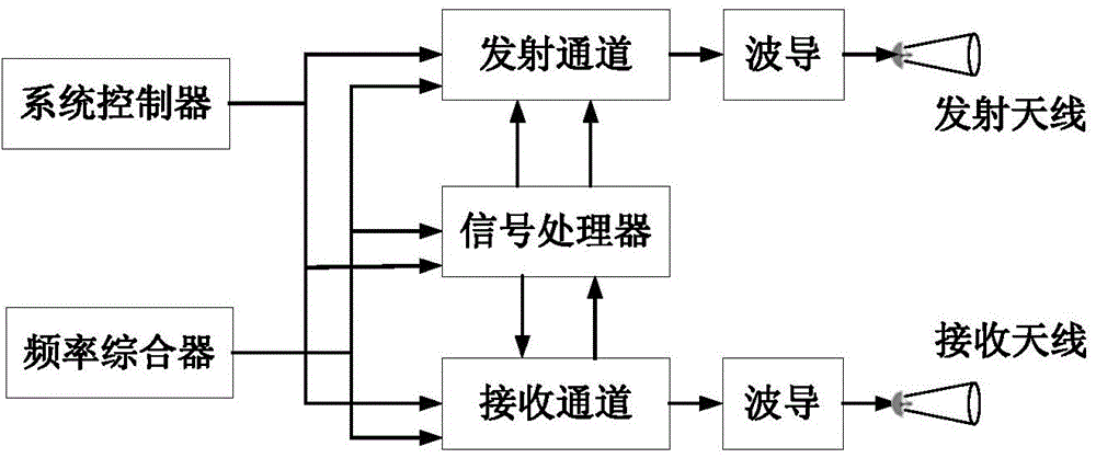
[0041] Such as figure 1 As shown, the microwave ranging radar system of the present invention includes a system controller, a frequency synthesizer, a signal processor, a transmitting channel, a receiving channel, a waveguide and an antenna.

[0042] The system controller sends a work start control signal to the digital signal processor, and the digital signal processor starts to work to generate the required radar transmission waveform signal. The transmission signal is converted to radio frequency frequency through the transmission channel, and then transmitted through the power amplifier and antenna . After the echo signal is received by the receiving antenna, it is fed into the receiving channel for amplification and down-conversion, and sent to the digital signal processor for A / D sampling and related processing. At the same time, th...


PUM


Abstract

The invention discloses a design method for a wide-range high-precision microwave distance measurement radar system. In regard to the design problem of the wide-range high-precision radar system, the design method comprises the following steps that 1, by means of waveform and time sequence design, remote measurement transmitting and receiving work in a time-sharing mode, large bandwidth and time-bandwidth signals are adopted in close distance measurement, and transmitting and receiving work at the same time; 2, the design of isolating a transmitting access and a receiving access is adopted to ensure that back waves can be collected and received effectively; 3, by means of the transmitted leakage signal removal technology, influence on back wave detection from close distance transmitted leakage signals can be restrained. By the adoption of pulse radar, the measurement range of 15 m to 16 km and the measurement precision of 0.33%*R when the range is larger than 120 m, and of 0.4 m when the range is smaller than 120 m are achieved.

Description

technical field [0001] The invention relates to a wide-range high-precision microwave ranging radar system, which belongs to the technical field of space microwave radar measurement. Background technique [0002] The development of the microwave ranging radar project is derived from the model development of the microwave ranging and speed measuring sensor of the GNC subsystem of Chang'e-3 in the second phase of the lunar exploration project, which provides distance information for the landing and descent process. The measurement range requires 15m-16km, and the accuracy requires 0.33 over 120m. %*R, 0.4m below 120m. [0003] At present, the long-range radar mainly uses the pulse system, and the short-range radar measurement technology mainly includes frequency modulation continuous wave and narrow pulse measurement technology. [0004] The pulse measurement technology is to measure the distance by calculating the delay between the received signal and the transmitted signal....

Claims


Application Information

Patent Timeline
Patent Type & Authority Applications(China)
IPC IPC(8): G01S7/28
CPCG01S7/28G01S13/003G01S13/08
Inventor 刘瑞冬谭小敏党红杏王科张爱军牛文博孙嘉
Owner XIAN INSTITUE OF SPACE RADIO TECH
Learn More