Grouting pressure stabilizing device and mounting method

A technology of grouting pressure and stabilizing device, which is applied in the directions of fluid pressure actuating device, fluid pressure actuating system components, vertical shaft equipment, etc., can solve the problem that the grouting pump cannot be used together.

Active Publication Date: 2014-07-30
SHANDONG UNIV
View PDF6 Cites 4 Cited by
  • Summary
  • Abstract
  • Description
  • Claims
  • Application Information

AI Technical Summary

Problems solved by technology

[0004] In the patent No.: 200720101956.6, an adjustable high-pressure grouting device is disclosed. This device can only be used for grouting, and it cannot be used in conjunction with the grouting pump, and the grout output by the grouting pump cannot be matched with the pressure. The area is gentle and significantly reduces the fluctuation characteristics of grouting pump grouting pressure and flow rate

Method used


Image

  • Grouting pressure stabilizing device and mounting method
  • Grouting pressure stabilizing device and mounting method

Examples


Embodiment Construction

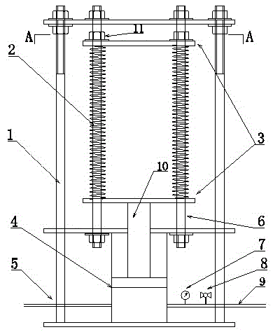
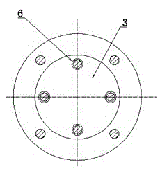
[0025] refer to figure 1 , figure 2 , The grouting pressure stabilizing device comprises three parts: a slurry buffer cylinder 4, an energy storage device and a fixed bracket 1. The upper part of the bracket is provided with an energy storage device, and the lower part is provided with a slurry buffer cylinder. One end of the energy storage device It is fixed on the bracket, and the other end is connected with the top of the slurry buffer rod.

[0026] The energy storage device includes two guide plates 3, guide rails 6 and several springs 2 fixed in the guide rails, the two ends of the springs 2 are fixed to the guide plates, and the upper guide plate 3 is fixed on the guide rails 6 by adjusting bolts 11. , the lower guide plate 3 is fixed to the slurry buffer rod 10;

[0027] By adjusting the position of the bolt 11 on the guide rail 6, the length and force of the spring 2 can be changed, so as to adjust the slurry flow rate and pressure fluctuation range of the device. ...


PUM


Abstract

The invention specifically discloses a grouting pressure stabilizing device and a mounting method. The grouting pressure stabilizing device comprises a bracket, wherein an energy storing device is arranged on the upper part in the bracket; a serous fluid buffering cylinder is arranged on the lower part; one end of the energy storing device is fixed on the bracket while the other end is connected with a piston of the serous fluid buffering cylinder; the energy storing device comprises two guiding plates, guide rails and a plurality of springs fixed between the two guiding plates; the guiding plates and the springs can move back and forth along the guide rails under an effect of grouting pressure; the springs fixed between the two guiding plates are rotationally symmetrically distributed about an axial central line of the two guiding plates. During a working process, when the grouting pressure is rapidly increased, the springs are compressed by the serous fluid through a piston rod and the energy storage of the energy storing device and the energy-consuming pressure reduction of the serous fluid are realized, and when the grouting pressure is rapidly reduced, the elastic potential energy is released by the compressed springs and the energy-increasing pressure boosting of the serous fluid is realized.

Description

[0001] technical field [0002] The invention relates to a grouting pressure stabilizing device and an installation method, belonging to the field of water conservancy and hydropower, tunnel and mine grouting reinforcement and seepage prevention and water blocking engineering. Background technique [0003] At present, the grouting in water conservancy and hydropower, tunnel, mine grouting reinforcement and anti-seepage and water plugging engineering fields mostly uses piston type grouting pump, and the grouting pressure and grouting flow fluctuate in pulse form; it not only limits the grouting pressure during the grouting process Improve and weaken the anti-seepage effect of grouting reinforcement, and make the surrounding rock subject to significant periodic grouting pressure (dynamic force), which is easy to induce instability and destruction of the surrounding rock. The grouting pressure and flow stabilization device can significantly suppress the fluctuation of grouting ...

Claims


Application Information

Patent Timeline
Patent Type & Authority Applications(China)
IPC IPC(8): F15B1/02F15B21/14E21D11/10E21D11/38
Inventor 朱明听张庆松张霄李志鹏王德明翁贤杰李鹏
Owner SHANDONG UNIV
Why Eureka
Try Eureka