an air drill

An air drill and drill bit technology, which is used in repairing drills, drilling tool accessories, portable drilling rigs, etc., can solve the problems of no dust removal device, dislocation of punching points, excessive chips and powders, etc., and achieves simple and reliable structure and punching point position. Precise, rounded hole cuts

Active Publication Date: 2016-03-02
HEBEI DELE MACHINERY TECH
View PDF2 Cites 0 Cited by
  • Summary
  • Abstract
  • Description
  • Claims
  • Application Information

AI Technical Summary

Problems solved by technology

Ordinary air drills use solid drill bits, which have a large cutting force and a large reaction force on the material, which is easy to deform the material. When it is applied to easy-to-deform and soft hollow thin-walled materials, it is easy to shift the drilling position when drilling online. and hole deformation defects, so that the incision deformation is irregular and the shape of the cutting hole is destroyed, and more chips and powder are generated during the drilling process. During the chip removal process, the chip particles and powder are easily lifted by the drill bit, and the generated dust will Pollution to the working environment and harmful to human health
[0003] The Chinese patent that the patent number is 03156900.5 discloses a kind of air drill, and its drill bit is a solid drill bit, which can be used for punching holes in hard materials such as ordinary wood or metal. And generate dust, the rotation direction of the drill bit is divided into positive and negative, no dust removal device
However, even if the sealing strip with a hollow and thin-walled structure does not slide as a whole, during the drilling process, the solid drill bit will touch the surface of the material and the drill bit enters the interior of the material. The pressure and the friction force pointing to the inside of the material along the axial direction of the drill bit will cause the thin-walled material to deform and slip, resulting in the dislocation of the punching point and the deformation of the hole
As the drill bit enters the material, the contact surface between the side cutting edge of the drill bit and the material increases, and the shear force on the material increases, which is more likely to cause deformation of the material, thereby destroying the shape of the cut hole.

Method used


Image

  • an air drill
  • an air drill
  • an air drill

Examples


Embodiment 1

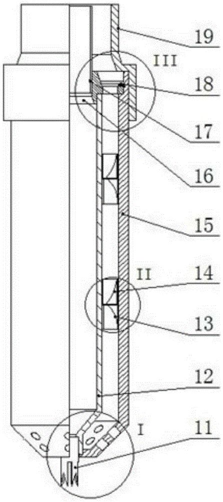
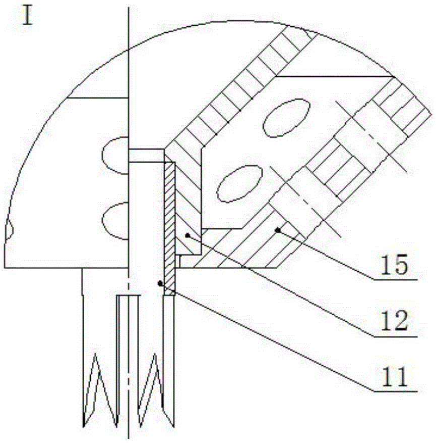
[0026] In this embodiment, the drill bit 11 is an axially penetrating hollow drill bit (see image 3 ), and is provided with a cutting edge at the lower end. The drill bit 11 includes 3 sets of cutting edges. The shape of a single set of cutting edges is "M". There is a gap between two adjacent sets of cutting edges. The ratio of the gap width to the cutting edge width is 0.5 , The ratio of clearance depth to cutting edge depth is 2.

[0027] Sleeve 15 (see figure 2 , image 3 with Figure 5 ) There are 15 vent holes in the front section, and the inner cylinder wall at the inner end of the end is provided with an annular groove for installing the elastic retaining ring 18. The side of the annular groove opposite to the air distribution plate 16 is an inclined surface and is connected to the air distribution plate 16 The radial plane is 45°.

[0028] Guide impeller 13 and rotor impeller 14 (see figure 2 with Figure 4 ) Are ring-shaped, with 30 blades in the circumferential direct...

Embodiment 2

[0032] In this embodiment, the drill bit 11 includes 5 groups of cutting edges. The shape of a single group of cutting edges is "M". There is a gap between two adjacent groups of cutting edges. The ratio of the gap width to the cutting edge width is 0.3. The depth ratio is 3.

[0033] The sleeve 15 has 20 vent holes in its front section. The inner cylinder wall at the inner end of the sleeve 15 is provided with an annular groove for installing the elastic retaining ring 18. The side of the annular groove opposite to the air distribution plate 16 is an inclined surface and is connected to The radial plane of the gas disk 16 is 30°.

[0034] The guide impeller 13 and the rotor impeller 14 are provided with 25 blades in the circumferential direction. The blades are at 45° to the axial direction. The rotor impeller 14 and the guide impeller 13 are provided with gaps on the opposite end faces, and the blades of the two are in opposite directions. The number of guide impellers 13 and ro...

Embodiment 3

[0038] In this embodiment, the drill bit 11 includes two groups of cutting edges. The shape of a single group of cutting edges is "M". There is a gap between two adjacent groups of cutting edges. The ratio of the gap width to the cutting edge width is 1. The ratio of depth is 1.3.

[0039] The sleeve 15 has 10 vent holes in its front section. The inner cylinder wall at the inner end of the sleeve 15 is provided with an annular groove for installing the elastic retaining ring 18. The side of the annular groove opposite to the air distribution plate 16 is an inclined surface and is connected to The radial plane of the gas disk 16 is 60°.

[0040] The guide impeller 13 and the rotor impeller 14 are provided with 18 blades in the circumferential direction, and the blades are at 60° to the axial direction. The rotor impeller 14 and the guide impeller 13 are provided with gaps on the opposite end faces, and the blades of the two are in opposite directions. The number of guide impellers ...


PUM


Abstract

The invention relates to a pneumatic drill. The pneumatic drill comprises an air filter and an air pump. The pneumatic drill is characterized in that the pneumatic drill further comprises a negative-pressure pneumatic drill and a chip separator, wherein the negative-pressure pneumatic drill, the chip separator, the air filter, and the air pump are sequentially connected into a whole through air pipes; the negative-pressure pneumatic drill comprises a drill bit, a rotor blade holder, guide impellers, rotor impellers, a sleeve, a gas distribution disc, a casing pipe, an elastic retainer ring and an air pipe connector, wherein the chip separator comprises a lower housing, an upper housing, a chip accommodating bottle and separating impellers. The pneumatic drill provided by the invention not only achieves the function of the pneumatic drill, but also achieves the function of automatic online punching of deformable and soft hollow thin-walled materials; positions of the punching points are accurate and the incision of punching holes is round and uniform; chips and powders produced during the working process are less, so that the pneumatic drill has the advantage of high efficiency and environmental protection. The hollow drill bit is adopted and each group of cutting edges has the same shapes; the chips are discharged from the interior. Therefore, regardless of the positive direction or the reverse direction, a reversing valve is not required; the structure is simpler and more reliable.

Description

Technical field [0001] The invention relates to a punching device, in particular to an air drill. Background technique [0002] The application range of ordinary gas drills in the prior art has limitations. Ordinary air drills use solid drills, which have a large cutting force and a large reaction force to the material, which is easy to deform the material. It is easy to cause the drilling position to shift when it is applied to the online drilling of easily deformable and soft hollow thin-walled materials. And the defects of hole deformation, which make the incision deformed irregularly, destroy the shape of the cut hole, and produce more chips and powder during the drilling process. The chip particles and powder are easily raised by the drill bit during the chip removal process, and the generated dust will be It causes certain pollution to the working environment and is harmful to human health. [0003] The Chinese patent No. 03156900.5 discloses a pneumatic drill. The drill bi...

Claims


Application Information

Patent Timeline
Patent Type & Authority Patents(China)
IPC IPC(8): B23B45/04B23B47/34B23B51/00B26F1/16B26D7/18
CPCB23B45/04B23B47/34B23B51/00B26D7/1863B26F1/16
Inventor 肖艳军王大源关玉明
Owner HEBEI DELE MACHINERY TECH
Why Eureka
Try Eureka