
A Coating-Based Pulse Sequence Modulator

A pulse sequence and modulator technology, applied in the field of ultrafast laser pulse sequence modulation method and modulator, can solve the problems of high cost, slow modulation speed, low damage threshold, etc., achieve low cost, improve reliability and stability, The effect of reducing system complexity and cost

Active Publication Date: 2016-08-31
BEIJING INSTITUTE OF TECHNOLOGYGY
View PDF7 Cites 0 Cited by
  • Summary
  • Abstract
  • Description
  • Claims
  • Application Information

AI Technical Summary

Problems solved by technology

[0004] The purpose of the present invention is to overcome the disadvantages of complex structure, low damage threshold, high cost, and slow modulation speed of the commercial pulse shaper system and to solve the problems of complex optical path structure and difficult alignment adjustment existing in conventional spectroscopic methods. pulse train modulator

Method used


Image

  • A Coating-Based Pulse Sequence Modulator
  • A Coating-Based Pulse Sequence Modulator
  • A Coating-Based Pulse Sequence Modulator

Examples


Embodiment 1

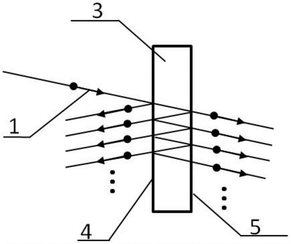
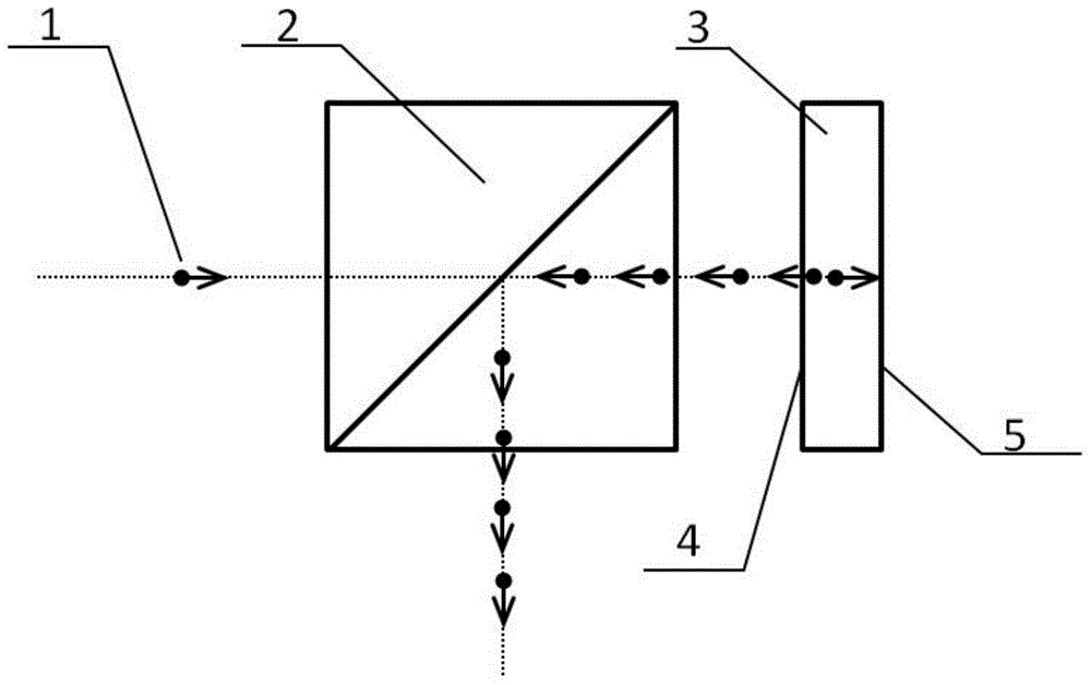
[0028] A coating-based pulse sequence modulator includes: an ultrafast laser pulse 1, a beam splitter 2, a modulation lens 3, a front surface 4, and a rear surface 5.

[0029] The connection relationship is:

[0030] After the ultrafast laser pulse 1 passes through a beam splitter 2 placed at 45 degrees to the laser propagation direction, it is vertically incident on the front surface 4 of the modulation lens 3, then passes through the modulation lens 3 to the rear surface 5, and passes through the modulation lens 3. After modulation, a beam of pulse sequence is reflected back from the front surface 4 and propagates along the direction opposite to the incident laser. This beam of pulse sequence is reflected after encountering the mirror 2 and separated from the incident laser. Direction output, both the front surface 4 and the rear surface 5 of the modulation lens 3 are coated with a semi-transparent and semi-reflective film;

[0031] The base material of the modulated lens 3...

Embodiment 2

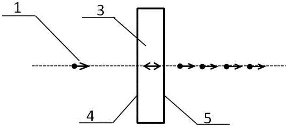
[0038] A pulse sequence modulator based on coating, comprising: 1—ultrafast laser pulse, 3—modulation mirror, 4—front surface, 5—rear surface.

[0039] The connection relationship is:

[0040] The ultrafast laser pulse 1 is vertically incident on the front surface 4 of the modulation lens 3 , and reaches the rear surface 5 after passing through the modulation lens 3 .

[0041] The material of the modulation lens 3 in this embodiment is N-BK7, the thickness is 100um, the front surface 4 is coated with a layer of broadband dielectric film, the reflectivity in the 700-920 wavelength range is 40%, and the rear surface 5 is coated with a layer of A dielectric film with a reflectivity of 50% in the wavelength range of 700-920. When inputting a femtosecond laser with a center wavelength of 800 nm and a pulse width of 50 fs, the delay of adjacent sub-pulses in the pulse train output from the rear surface 5 is 1 ps, and the energy ratio of each sub-pulse is: 100:20:5:1: ....

[0042...


PUM


Abstract

The invention relates to an ultra-fast laser pulse sequence modulation method and modulator, and belongs to the field of ultra-fast lasers. The modulator comprises ultra-fast laser pulses, a modulation lens, a front surface and a rear surface. The ultra-fast laser pulses perpendicularly enter the front surface of the modulation lens in an incidence mode and reach the rear surface after transmitting the modulation lens, the front surface and the rear surface of the modulation lens are respectively coated with a semi-transparent semi-reflection film, and a pulse sequence modulated by the modulation lens is output from the rear surface. The pulse sequence with specific femtosecond to picosecond magnitude time delay and a specific energy distribution rule can be directly generated only through one lens with the double surfaces coated with the films, a complex light path is not needed, an adjusting mechanism is not arranged, the processes of light path alignment, adjustment, correction and the like are omitted, system complexity and cost are greatly lowered, and reliability and stability are improved.

Description

technical field [0001] The invention relates to an ultrafast laser pulse sequence modulation method and a modulator, belonging to the field of ultrafast lasers. Background technique [0002] Ultrafast laser has the characteristics of short duration and high peak power (LanJiang, LisanLi, SumeiWangandHai-LungTsai. Microscopic energy transport through photon-electron-photon interactions during ultrashort laser ablation of wide band gap materials. China Laser. Vol.36, No.4.2009.), has strong excitation, control and detection Therefore, it has important applications in the fields of ultrafast chemistry (AH Zewail-Femtochemistry: Atomic-scale dynamics for the chemical bond. The Journal of Physical Chemistry A, 2000.), ultrafast biology and ultrafast laser manufacturing. Recently, in the field of ultrafast laser manufacturing, based on the idea of ​​electronic state regulation Realize high-precision, high-quality, high-efficiency manufacturing (LJiang, PLiu, XYan, NLeng, CXu, HXia...

Claims


Application Information

Patent Timeline
Patent Type & Authority Patents(China)
IPC IPC(8): H01S3/10
Inventor 姜澜余彦武曹强
Owner BEIJING INSTITUTE OF TECHNOLOGYGY
Learn More