Optical switch array and optical path device with the functions of projection and camera shooting

An optical switch array and optical switch technology, applied in optics, optical components, camera body, etc., can solve the problems of short life of color wheel motor, poor contrast of display screen, expensive CCD, etc., to achieve good screen contrast and low cost The effect of reduction and function expansion

Inactive Publication Date: 2014-07-16
JILIN UNIV
View PDF7 Cites 11 Cited by
  • Summary
  • Abstract
  • Description
  • Claims
  • Application Information

AI Technical Summary

Problems solved by technology

[0002] The functions of the existing display devices and camera devices are unitary, the reason is that the optical path design itself has a single function
Therefore, traditional display equipment can only be used for display, while traditional camera equipment can only be used for video recording, which cannot meet the needs of modern consumers for product versatility and convenience.
In terms of cost, the CCD used in the camera is expensive, and the DMD used in the DLP projector is only produced by Texas Instruments in the world, and the color wheel motor used in it also has the problem of short life.
The LCD screen of the LCD projector is easy to age
In addition, projection bulbs are relatively expensive and have a short lifespan. The projector consumes a lot of energy and needs heat dissipation when it is working. The contrast of the display screen is poor, and it is difficult to use it in a strong light environment.
Moreover, these projection devices are relatively large and not easy to carry.

Method used


Image

  • Optical switch array and optical path device with the functions of projection and camera shooting
  • Optical switch array and optical path device with the functions of projection and camera shooting
  • Optical switch array and optical path device with the functions of projection and camera shooting

Examples


Embodiment 1

[0026] Embodiment 1 Embodiment of "T" shaped optical switch

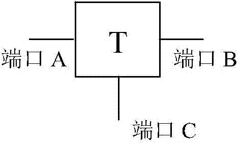
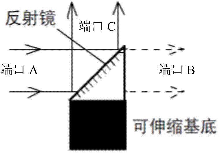
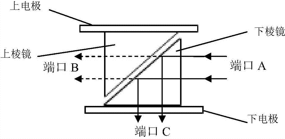
[0027] Please refer to figure 1 , 2 , 3, Figure 1 The structure and function of the "T" shaped optical switch are shown. It has three ports. Port A and port B are on the same straight line. The direction of port C is perpendicular to the straight line where port A and port B are located. This optical switch has optical path conversion Function, the light entering from port A can be controlled to choose to exit from port B or port C; figure 2 , 3 It is the concrete embodiment of two kinds of micromechanical "T" shaped optical switches.

[0028] figure 2 The "T"-shaped optical switch is mainly composed of a stretchable base and a reflector. The stretchable base can be composed of an electromagnet and an armature sandwiching an elastic material. The reflector is fixed on the armature, so that by controlling the electrical signal applied to the base The state of the optical switch can be controlled: when the co...

Embodiment 2

[0030] Embodiment 2 "T" shape optical switch array embodiment

[0031] Please refer to figure 1 with Figure 4 , the optical switch array is composed of multiple figure 1 The "T" shaped optical switch shown is formed by combining connections. figure 1A plurality of such "T" optical switches (the lower limit is 1 and the upper limit is not limited) are connected in sequence, and the port B of the first "T" optical switch is connected to the port A of the second "T" optical switch. The port B of the second "T" shaped optical switch is connected to the port A of the third "T" shaped optical switch, and so on, all the ports C of the "T" shaped optical switches point to the same direction, so that Form an optical switch chain. In the three-dimensional Cartesian space coordinates, one optical switch chain is placed along the y-axis. For the convenience of expression, it is called the y-chain. Any number of optical switch chains is placed along the z-axis. For the convenience of ...

Embodiment 3

[0032] Embodiment 3 An embodiment of an optical path device with both projection and camera functions

[0033] Please refer to Figure 5 with Image 6 , for the sake of convenience, here the optical switch array 8 adopts a structure of 8 rows×8 columns, and the principles of other structures are similar. The "column address signal" terminal and "row address signal" of the drive module 2 (here composed of two serial-in parallel-out chips 74HC595), the control terminal of the display light source 3, and the electrical signal output terminal of the photosensitive unit 4 are respectively connected with the processing The different input / output ports of device 1 (STC89C51 is selected here) are connected, and the display light source 3 here can be composed of a group of three primary color LED light sources or laser light sources and a light mixer. When projecting, the processor 1 controls the display light source 3 to emit light of a specific color according to the information of...


PUM


Abstract

The invention belongs to the field of projector and camera manufacturing, and particularly discloses an optical switch array and an optical path device with the functions of projection and camera shooting formed by the optical switch array. The optical switch array comprises an optical switch chain which is arranged along the y axis in the three-dimensional rectangular coordinate system and a plurality of T-shaped optical switch chains which are arranged parallel to the z axis. The optical path device with the functions of projection and camera shooting comprises a processor (1), a driving module (2), a display light source (3), a photoconductor unit (4), a light path separation unit (5), a divergent unit (6) and a lens module (7). The optical path device with the functions of projection and camera shooting is characterized in that the optical device is further provided with the optical switch array (8), and through controlling of the status of each 'T'-shaped optical switch in the optical switch array (8), direct projection display and scenery shooting are achieved. According to the optical switch array and the optical path device with the functions of projection and camera shooting, the structure is simple, the running power consumption is low, service life is long, the display color gamut is about the same as a laser television, the image quality is high, and the function of the projection and the function of the camera shooting are integrated.

Description

technical field [0001] The invention belongs to the technical field of projector and camera manufacturing, and in particular relates to an optical switch array and an optical path device composed of the array and having both projection and camera functions. Background technique [0002] The functions of the existing display devices and imaging devices are all unitary, and the reason is that the optical path design itself has the unitary function. Therefore, traditional display devices can only be used for display, while traditional camera devices can only be used for video recording, which cannot meet the needs of modern consumers for product versatility and convenience. In terms of cost, the CCD used in the camera is expensive, and the DMD used in the DLP projector is only produced by Texas Instruments in the world, and the color wheel motor used in it also has the problem of short life. The LCD screen of an LCD projector is prone to aging. In addition, projection bulbs a...

Claims


Application Information

Patent Timeline
IPC IPC(8): G02B26/08G03B17/54G03B30/00
Inventor 王广军龙国徽吴香英纪媛庞明俊汪东雪罗阳
Owner JILIN UNIV
Why Eureka
Try Eureka