
A test method for low-voltage control mode of converter valve control equipment

A technology for controlling equipment and control modes, applied in the direction of electronic circuit testing, etc., can solve the problems of inaccurate testing, inability to directly control triggering and monitoring, complicated testing process, etc., and achieve the effect of early detection

Active Publication Date: 2016-10-05
XUJI GRP +3
View PDF6 Cites 0 Cited by
  • Summary
  • Abstract
  • Description
  • Claims
  • Application Information

AI Technical Summary

Problems solved by technology

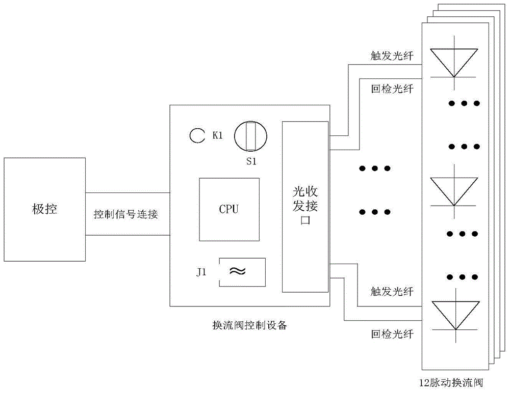
[0004] The purpose of the present invention is to provide a test method for the low-voltage control mode of the converter valve control equipment, so as to solve the problem that the existing converter valve control equipment cannot directly control the trigger and monitor the thyristor during the low-voltage test, which leads to a complicated test process and inaccurate testing The problem

Method used


Image

  • A test method for low-voltage control mode of converter valve control equipment
  • A test method for low-voltage control mode of converter valve control equipment
  • A test method for low-voltage control mode of converter valve control equipment

Examples


Embodiment Construction

[0019] The specific embodiments of the present invention will be further described below in conjunction with the accompanying drawings.

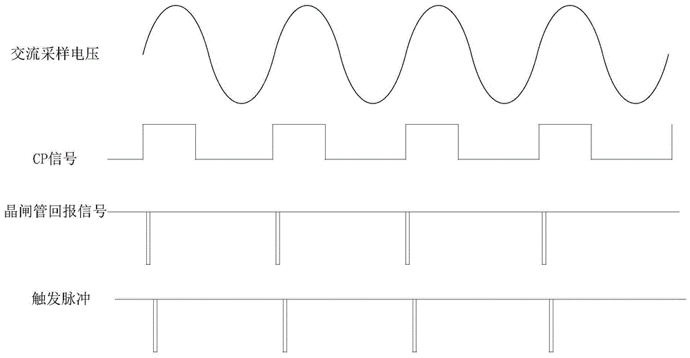
[0020] When the normal mode is running, when the valve control system receives the unlocking signal of the extreme control and is valid, the control enters the unlocking state. In the unlocked state, two conditions need to be met for the valve control device to send trigger pulses to the thyristor control board. One is to receive the CP signal (trigger control pulse signal) from the extreme control, and the other is to receive the thyristor forward voltage establishment signal from the thyristor control board. According to different voltage levels, the number of thyristors in a single valve is different. The valve control system generally receives a return signal from more than 70% of the thyristors in a single valve (specific projects, different parameters), and then determines that the forward voltage of the valve is established. At this...


PUM


Abstract

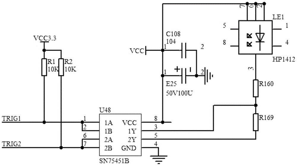
The invention relates to a method for testing a converter valve control device in a low-voltage control mode, and belongs to the technical field of extra-high voltage direct current transmission. CP signals are generated by the converter valve control device by sampling alternating voltages applied to thyristors, the converter valve control device triggers the thyristors according to return signals of the thyristors and the generated CP signals, whether the corresponding thyristors are connected or not is judged, and then the converter valve control device is tested in the low-voltage control mode. The method for testing the converter valve control device can be achieved through self configuration of the converter valve control device, and a converter valve can simulate a normal operating state in the low-voltage environment to meet testing and debugging requirements. When the converter valve control device is tested in the low-voltage control mode, the power of light trigger pulses sent to the converter valve thyristors by the converter valve control device is smaller than the power of light trigger pulses sent by the converter valve control device in the normal operating state, and therefore potential safety hazards of system elements can be found in advance.

Description

technical field [0001] The invention relates to a test method for a low-voltage control mode of a converter valve control device, and belongs to the technical field of ultra-high voltage direct current transmission. Background technique [0002] In UHV DC transmission, the converter valve control equipment is the core control equipment for the operation of the converter valve. Its main function is to receive the control command issued by the extreme control, analyze and encode the control command, and send the recoded optical pulse signal to the thyristor control board of the converter valve to control the operation of the converter valve. Monitor the operating status of the converter valve. [0003] Due to the high voltage level of UHV DC projects, it is generally 800kV at present. Any fluctuation of the system may bring great harm to the regional power grid. As the core equipment of the converter station, the converter valve and valve control can be operated stably and ...

Claims


Application Information

Patent Timeline
Patent Type & Authority Patents(China)
IPC IPC(8): G01R31/28
Inventor 孟学磊魏卓宋建强樊宏伟罗鹏
Owner XUJI GRP
Learn More