
Reinforced concrete pole

A technology of reinforced concrete and concrete layers, applied in wind power generation, building types, buildings, etc., can solve the problems of pole body damage, shorten the service life of poles, and easily cause pole collapse, etc., and achieve good corrosion resistance, high strength, and structure simple effect design

Inactive Publication Date: 2017-02-08
GUANGXI UNIV
View PDF6 Cites 0 Cited by
  • Summary
  • Abstract
  • Description
  • Claims
  • Application Information

AI Technical Summary

Problems solved by technology

[0002] The concrete layer of existing reinforced concrete poles is divided into hollow and solid. The hollow concrete layer pole has the advantages of high strength and durability in a dry and non-corrosive environment, but it is used in a saline-alkali corrosive environment. Because the pole is in the saline-alkali liquid for a long time, the inner and outer walls of the pole are often eroded, and the pole is prone to collapse. In low-lying areas, there is often water accumulation inside the pole body. Once it comes to winter, the pole body is prone to damage under the action of freeze-thaw cycles. , thereby greatly shortening the service life of the pole; although the solid concrete pole can solve the above problems, it brings new problems. The solid concrete pole uses more concrete, which increases the production cost and increases The overall weight of the pole is not conducive to the handling and transportation of the pole; moreover, the poles are generally erected in sparsely populated areas. Due to the increase in the service life and the serious exploitation of groundwater resources, the poles will tilt, causing serious safety hazards. Hidden danger

Method used


Image

  • Reinforced concrete pole
  • Reinforced concrete pole
  • Reinforced concrete pole

Examples


Embodiment Construction

[0017] Below we describe in further detail the specific implementation cases of the present invention in conjunction with the accompanying drawings:

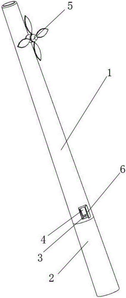
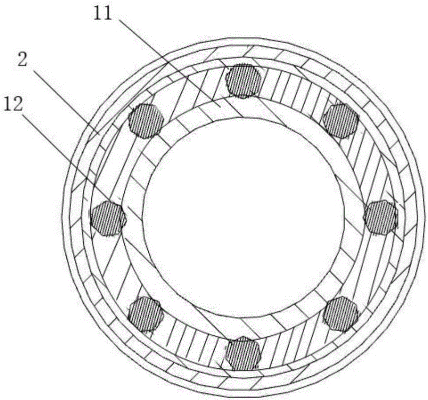
[0018] Such as figure 1 As shown, a reinforced concrete pole includes a pole body 1, a detection and alarm system and a ceramic layer 2, and the detection and alarm system is arranged on the pole body 1; as image 3 As shown, the rod body 1 includes a hollow concrete layer 11 and a reinforcing steel structure layer 12, the concrete layer 11 is internally provided with a reinforcing steel structure layer 12; the lower part of the rod body 1 is wrapped with a layer of ceramic layer 2; Such as Figure 4 As shown, the circular array inside the ceramic layer 2 is provided with engaging parts 21, and there are 12 engaging parts 21 in three rows; the height of the ceramic layer 2 is 1.0m-2.0m. The detection and alarm system includes an angle sensor 3, an alarm device 4, and a wind power generation device 5. The angle sensor 3 and the...


PUM

PropertyMeasurementUnit
heightaaaaaaaaaa

Abstract

The invention belongs to the technical field of a pole and discloses a reinforced concrete pole. The reinforced concrete pole comprises a pole body and a detection alarming system, wherein the detection alarming system is arranged on the pole body; the pole body comprises a hollow concrete layer, a reinforced steel bar reinforcing layer and a ceramic layer; the reinforced steel bar reinforcing layer is arranged in the concrete layer; the ceramic layer is wrapped on the lower part of the pole body; the detection alarming system comprises an angle sensor, an alarm device and a wind power generation device; the angle sensor and the alarm device are arranged on the lower part of the pole body and are adjacent to the ceramic layer; the wind power generation device is arranged at the top end of the pole body; the alarm device is connected with the angle sensor and the wind power generation device respectively. The reinforced concrete pole is simple in structure design, has excellent anti-corrosion property and high strength, is equipped with an independent detection alarming system and is capable of finding the potential safety hazard in advance.

Description

technical field [0001] The invention belongs to the technical field of electric poles, in particular to a reinforced concrete electric pole. Background technique [0002] The concrete layer of existing reinforced concrete poles is divided into hollow and solid. The hollow concrete layer pole has the advantages of high strength and durability in a dry and non-corrosive environment, but it is used in a saline-alkali corrosive environment. Because the pole is in the saline-alkali liquid for a long time, the inner and outer walls of the pole are often eroded, and the pole is prone to collapse. In low-lying areas, there is often water accumulation inside the pole body. Once it comes to winter, the pole body is prone to damage under the action of freeze-thaw cycles. , thereby greatly shortening the service life of the pole; although the solid concrete pole can solve the above problems, it brings new problems. The solid concrete pole uses more concrete, which increases the producti...

Claims


Application Information

Patent Timeline
Patent Type & Authority Applications(China)
IPC IPC(8): E04H12/12
CPCE04H12/12Y02E10/728
Inventor 谢林玲
Owner GUANGXI UNIV
Learn More