
Thin skin milling device and method for milling by utilizing device

A skin and milling technology is applied in the field of thin skin milling and cutting devices to achieve the effects of improving work efficiency, reducing use time, and reducing clamping time

Inactive Publication Date: 2014-07-16
AVIC SAC COMML AIRCRAFT
View PDF7 Cites 8 Cited by
  • Summary
  • Abstract
  • Description
  • Claims
  • Application Information

AI Technical Summary

Problems solved by technology

[0007] In order to solve the above-mentioned problems in the prior art, the present invention provides a thin skin milling device, which solves the problem that the thin skin cannot completely fit the vacuum platform through the effective cooperation of the vacuum platform and the profiling clamp. During the milling process, looseness and vibration occur, resulting in overcutting of the thin skin, affecting the processing accuracy of the skin and causing the skin to be scrapped.

Method used


Image

  • Thin skin milling device and method for milling by utilizing device
  • Thin skin milling device and method for milling by utilizing device
  • Thin skin milling device and method for milling by utilizing device

Examples


Embodiment Construction

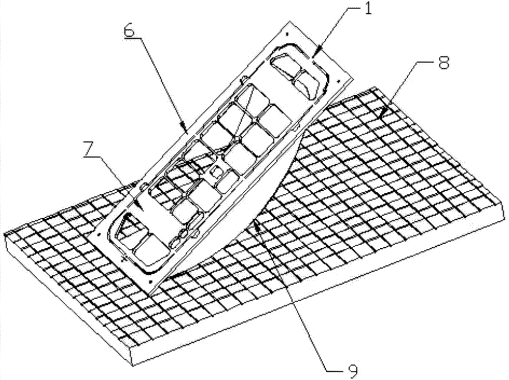
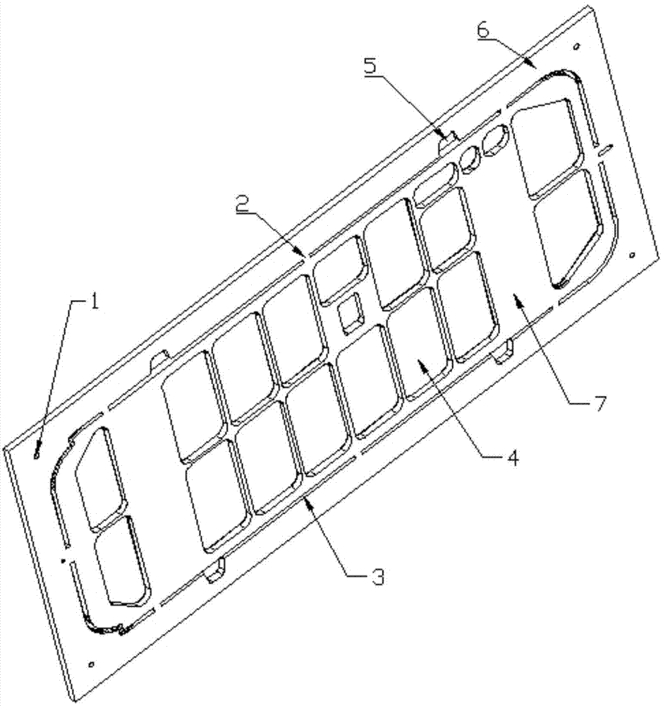
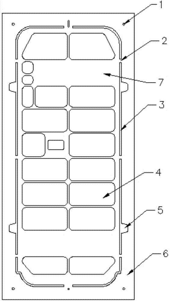
[0036] Such as Figure 1-3 A kind of thin skin milling device shown, comprises vacuum platform 8, Figure 2-3 Profile hold down fixture shown, thin skin 9. The thin skin 9 is placed on the vacuum platform 8, and the profiling clamp is placed on the thin skin 9. The surface area of ​​the vacuum platform 8 is larger than that of the profiling clamp, and the surface area of ​​the profiling clamp is larger than that of the thin skin 9. The surface area of ​​the profiling clamp is a rectangular thick aluminum plate. The surface plane of the thick aluminum plate near the edge has a cut-off groove 3 that matches the outer contour of the thin skin 9. The surface of the thick aluminum plate has a depression with the thin skin 9. For the sunken milling area 4 that matches the area, the profiling clamp has an outer contour pressing area 6 in the area outside the cutting 3, and an inner pressing area 7 in the area inside the cutting groove 3.

[0037] The surface of the vacuum platform ...


PUM


Abstract

The invention relates to a thin skin milling device. The thin skin milling device comprises a vacuum platform, thin skin and a profiling compression clamp, wherein the thin skin is arranged on the vacuum platform, the profiling compression clamp is arranged on the thin skin, the surface area of the vacuum platform is larger than that of the profiling compression clamp, and the surface area of the profiling compression clamp is larger than that of the thin skin; the profiling compression clamp is a rectangular thick aluminum plate, cutting troughs matched with the outer contour of the thin skin are formed in the periphery, close to the edge, of a surface plane of the thick aluminum plate, sunken milling regions matched with sunken regions of the thin skin are formed in the surface of the thick aluminum plate, an outer contour compression region is arranged at the region, outside of the cutting troughs, on the profiling compression clamp, and an interior compression region is arranged at the region, inside the cutting troughs, on the profiling compression clamp. By milling the skin by virtue of the thin skin milling device, the phenomenon that skin is scrapped due to the overcutting as the skin is intermittently desorbed from the vacuum platform and looses and shakes in a milling process can be effectively avoided.

Description

technical field [0001] The invention relates to the field of aviation numerical control machining of thin skins, in particular to a thin skin milling device and a milling method using the device. Background technique [0002] At present, the existing numerical control machining of aerospace thin skin is to use the cooperation of vacuum platform and pressing block to clamp the thin skin. The method is to put the rolled thin skin on the vacuum platform, The surrounding area of ​​the skin is pressed with briquettes, and the middle area relies on the vacuum pressure of the vacuum platform to absorb the thin skin, and then it is machined and milled. However, in the actual processing and production, this method is used to process thin skins, the qualified rate of thin skins is very low, and the phenomenon of thin skins overcut often occurs. [0003] If the thin skin is larger, the number of briquettes increases accordingly. This method not only greatly increases the time of manu...

Claims


Application Information

Patent Timeline
Patent Type & Authority Applications(China)
IPC IPC(8): B23C3/00B23Q3/08
Inventor 刘佳屈广浩吴靖中
Owner AVIC SAC COMML AIRCRAFT
Learn More