Tubular insertion device

An insertion device and tubular technology, applied in medical science, surgery, instruments, etc., can solve problems such as inability to know external force, enlarged cylindrical tube shape, and flexible obstacles

Active Publication Date: 2014-07-02
OLYMPUS CORP
View PDF9 Cites 8 Cited by
  • Summary
  • Abstract
  • Description
  • Claims
  • Application Information

AI Technical Summary

Problems solved by technology

[0006] In the above-mentioned Japanese Patent Application Laid-Open No. 2001-169998, the operator can know the shape of the pipe as the operation auxiliary information of the cylindrical pipe, but cannot know the information such as the external force applied to the pipe.
On the other hand, in the aforementioned Japanese Patent Application Laid-Open No. 6-154153, it is possible to detect an external force applied to a pipe from a specific direction, but if it is assumed that an external force is applied to the pipe from various directions, it is necessary to attach a very large number of deformation measuring devices
As a result, the outer shape of the cylindrical tube becomes larger, or the flexibility is hindered due to the installation of a large number of wiring and sensors, or there are problems such as the need for bulky wiring for sensors.

Method used


Image

  • Tubular insertion device
  • Tubular insertion device
  • Tubular insertion device

Examples


no. 1 Embodiment approach

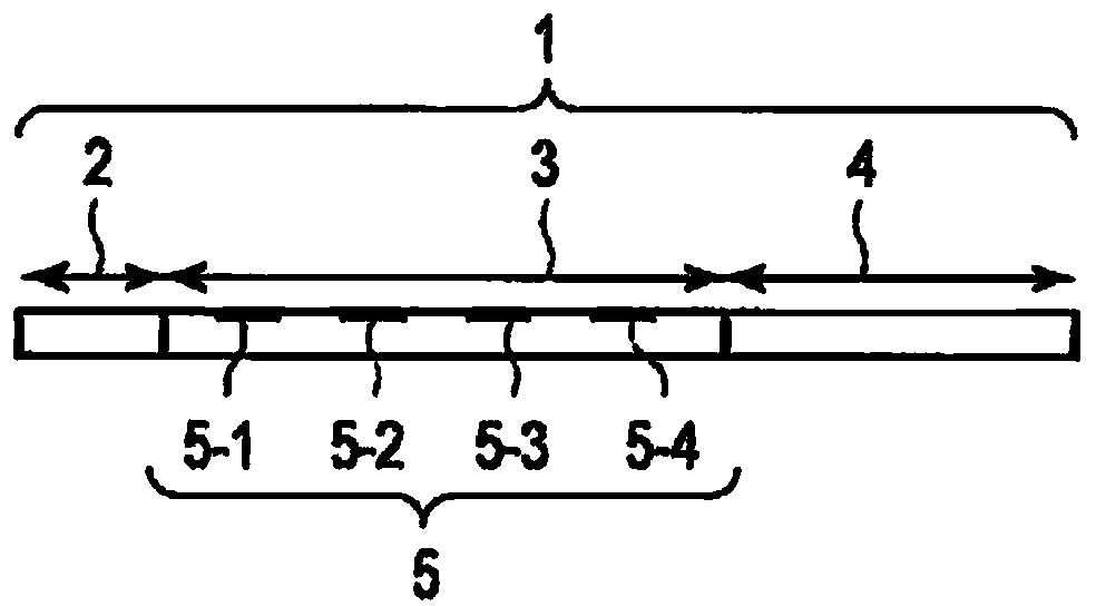
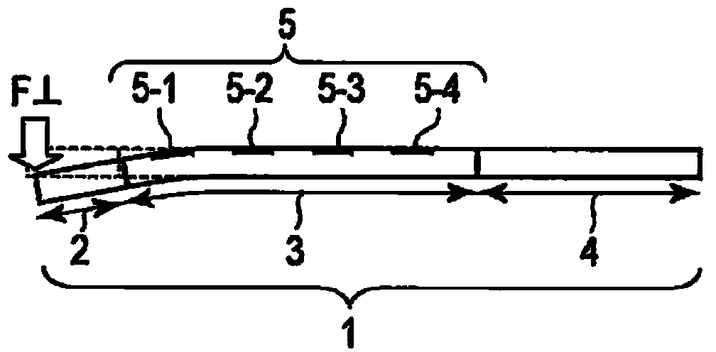
[0034] First, refer to Figure 1A to Figure 1H The principle of external force detection in the tubular insertion device according to the first embodiment of the present invention will be described.

[0035] Here, a case where the tubular insertion part 1 includes the distal rigid part 2 , the flexible bending part 3 , and the quasi-rigid part 4 sequentially from the distal end with respect to the longitudinal direction, such as an endoscope, will be described. The tubular insertion part 1 is inserted into a lumen (not shown) by an operator. In the bending part 3, which is a flexible part, the bending detection parts 5-1, 5-2, 5-2, and 5-1 are distributed and arranged as a plurality of bending sensors of the bending detection part 5 at predetermined intervals in the longitudinal direction. 5-3, 5-4. Alternatively, a shape sensor that detects the bending state of the entire flexible portion of the bending portion 3 may be disposed as the bending detection portion 5 .

[0036...

no. 2 Embodiment approach

[0084] Hereinafter, a second embodiment of the present invention will be described in detail based on the drawings. In addition, the description of the common parts with the above-mentioned first embodiment will be omitted.

[0085] The tubular insertion device of the second embodiment, such as Figure 7 As shown, a bending operation part 40 is provided in order to be able to bend the tubular insertion part 1 with bending operation wires (wires) 21 and 22 . When the bending operation wires 21 and 22 are rotated by rotating the bending operation knobs 23 and 24 , the wire on the side connected to the rotated entanglement side is pulled. Here, the bending operation wire 21 is a bending operation wire for bending in the left-right (LR) direction, and the bending operation knob 23 is a bending operation knob for bending in the left-right (LR) direction. The bending operation wire 22 is a bending operation wire for bending in the up-down (UD) direction, and the bending operation ...


PUM


Abstract

A tubular insertion device includes a tubular insertion portion including a flexible portion in a predetermined part, bending sensors distributed and arranged in the flexible portion, and an operation support information calculating unit. The operation support information calculating unit extracts operation support information including at least first external force information regarding an external force applied to the tubular insertion portion by a combinational calculation based on detection information from the bending sensors.

Description

technical field [0001] The present invention relates to a tubular insertion device including a tubular insertion portion having a flexible portion at a predetermined portion. Background technique [0002] In a tubular insertion device for inserting a flexible cylindrical tube into a lumen, there is known a configuration in which the shape of the cylindrical tube is detected using an optical fiber for shape detection. For example, Japanese Unexamined Patent Publication No. 2001-169998 discloses a configuration in which a plurality of optical fibers for shape detection are arranged at predetermined intervals on the outer peripheral surface of a cylindrical tube, and these The optical fibers are connected together along the longitudinal direction of the cylindrical tube to combine the bending amounts of the plurality of bending detection points, thereby enabling detection of the shape of the entire cylindrical tube. [0003] In addition, a tubular insertion device for insertin...

Claims


Application Information

Patent Timeline
Patent Type & Authority Applications(China)
IPC IPC(8): A61B1/00G02B23/24
CPCG01N3/20G02B23/2476A61B1/0051A61B2034/2061A61B1/009
Inventor 山本英二东条良羽根润长谷川润
Owner OLYMPUS CORP
Why Eureka
Try Eureka