
Biomass fuel waste heat recycling cooking range

A biomass fuel and waste heat recovery technology, which is applied in the direction of stoves/stoves with hot water devices, household stoves/stoves, solid heating fuels, etc., can solve the adverse effects of the surrounding environment, low heat utilization rate, inconvenient use, etc. problem, to achieve the effect of simple structure, high heat absorption rate and high utilization rate

Active Publication Date: 2014-07-02
贺曼
View PDF9 Cites 3 Cited by
  • Summary
  • Abstract
  • Description
  • Claims
  • Application Information

AI Technical Summary

Problems solved by technology

[0003] At present, in the combustion furnace using biomass pellet fuel, the junction between the top of the furnace and the heating body is generally open or equipped with a chimney. The heat absorbed by the heating body is only about 20% of the heat generated by the fuel, and the remaining 80% of the heat is passed through the open. The exhaust port or chimney is emitted in the air, the heat utilization rate is low, and resources are wasted
Secondly, when the biomass pellet fuel is burned, the incompletely burned organic matter forms smoke and is discharged into the air, blocking the line of sight and having an adverse effect on the surrounding environment, especially when cooking with a biomass pellet fuel combustion furnace, the smoke blurs the vision of the human eye , inconvenient to use

Method used


Image

  • Biomass fuel waste heat recycling cooking range
  • Biomass fuel waste heat recycling cooking range
  • Biomass fuel waste heat recycling cooking range

Examples


Embodiment Construction

[0031] The present invention is described in detail below in conjunction with accompanying drawing and specific embodiment:

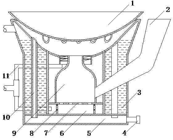
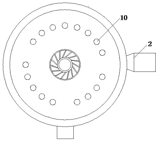
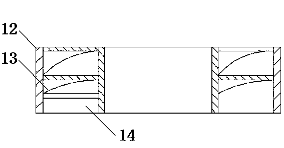
[0032] Such as figure 1 , figure 2 , image 3As shown, the biomass fuel waste heat recovery stove of the present invention includes a furnace 9 surrounded by high-temperature resistant materials and a blower; The bottom of the furnace bridge 7 is provided with an ash accumulation cavity 6 . The furnace is provided with a feed inlet, which extends outside the furnace wall through a tube or bucket 2 . The air outlet of the blower communicates with the ash chamber 6 through a pipeline. It also includes a waste heat recovery cavity 3 , a hot air pipe 10 and an induced draft fan 4 . The frying pan 1 is sealed and connected with the top of the hearth to form a heating zone. The waste heat recovery chamber is arranged around the furnace and isolated from the heating area on the top of the furnace. A steam outlet is provided on the top of the waste heat...


PUM


Abstract

The invention discloses a biomass fuel waste heat recycling cooking range which comprises a hearth defined by high temperature resistant materials and an air blower. A grate bridge is arranged at the bottom of the hearth, an opening for containing a heated body is formed in the top of the hearth, an ash accumulating cavity is formed below the grate bridge, a feeding opening is formed in the hearth and extends out of the wall of the hearth through a pipe or a hopper, and an air outlet of the air blower is communicated with the ash accumulating cavity through a pipe. The biomass fuel waste heat recycling cooking range further comprises a waste heat recycling cavity, hot air pipes and an induced draft fan. The heated body is connected with the top of the hearth in a sealed mode to form a heating area, the waste heat recycling cavity is arranged to surround the hearth and separated from the heating area at the top of the hearth, the hot air pipes are arranged in the waste heat recycling cavity, one ends of the hot air pipes extend out of the waste heat recycling cavity to be communicated with the heating area at the top of the hearth, and the other ends of the hot air pipes extend out of the waste heat recycling cavity to be communicated with the induced draft fan. The biomass fuel waste heat recycling cooking range is convenient to use, and heat generated by burning biomass particle fuel can be sufficiently used.

Description

technical field [0001] The invention relates to a heating device for burning fuel, in particular to a biomass fuel waste heat recovery stove. Background technique [0002] When the combustion furnace uses coal as fuel, harmful gases such as black smoke, carbon monoxide, sulfur dioxide, and nitrogen oxides will be emitted into the air, polluting the environment, and not conducive to human physical and mental health; while light diesel and natural gas are used as fuel or Using an electric furnace is expensive and the cost of use is high. Therefore, biomass pellet fuel is generally used, and the gas produced during the combustion of biomass pellet fuel is harmless. [0003] At present, in the combustion furnace using biomass pellet fuel, the junction between the top of the furnace and the heating body is generally open or equipped with a chimney. The heat absorbed by the heating body is only about 20% of the heat generated by the fuel, and the remaining 80% of the heat is pass...

Claims


Application Information

Patent Timeline
IPC IPC(8): F24B1/183F24B1/191
Inventor 贺曼
Owner 贺曼
Learn More