
Small-resistance anti-stall lifting device with vertical shaft needing to move vertically

A lifting device and vertical shaft technology, applied in the direction of lifting device, lifting frame, auxiliary device, etc., can solve the problems of large moving resistance of the upper and lower shafts, no safety guarantee for stalling, and hidden safety hazards, and achieve good safety and safety. Effect

Active Publication Date: 2014-07-02
TANGSHAN KAIYUAN AUTOWELDING SYST
View PDF6 Cites 17 Cited by
  • Summary
  • Abstract
  • Description
  • Claims
  • Application Information

AI Technical Summary

Problems solved by technology

[0002] Most of the large-load vertical shaft up and down moving devices currently used have no counterweight, transmit power through the trapezoidal screw, and have no brake lock device. Although the structure is simpler than this device, if the above device is driven by a servo motor, the The power requirement of the servo motor is much higher than that of the above-mentioned devices. Because the movement resistance of the upper and lower axes is large, and there is no safety guarantee when stalling, there are serious safety hazards

Method used


Image

  • Small-resistance anti-stall lifting device with vertical shaft needing to move vertically
  • Small-resistance anti-stall lifting device with vertical shaft needing to move vertically
  • Small-resistance anti-stall lifting device with vertical shaft needing to move vertically

Examples


Embodiment Construction

[0011] The present invention is described in detail below in conjunction with accompanying drawing and example.

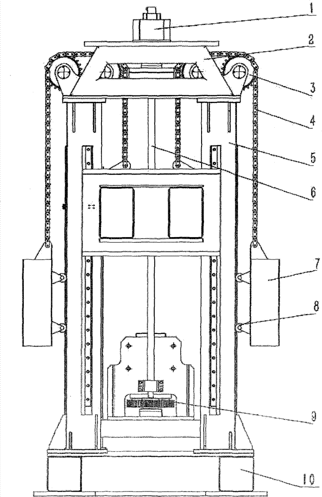
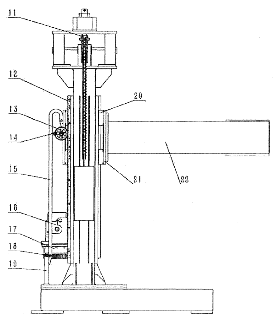
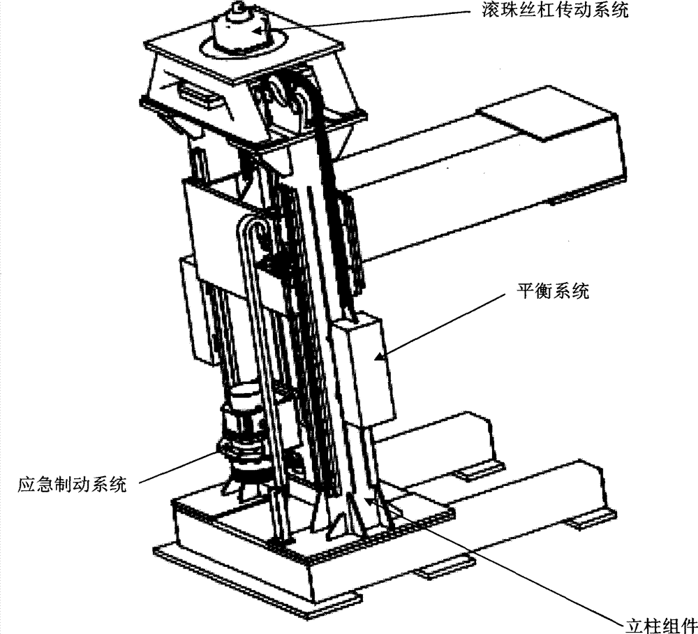
[0012] See attached figure 1 , figure 2 (main view), image 3 (left view), the device is mainly composed of column components (2, 5, 10, 21, 22), ball screw drive system (1, 6, 9, 11, 20), balance system (3, 4, 7, 8 ), emergency braking system (12, 13, 14, 15, 16, 17, 18, 19,).

[0013] In the ball screw transmission system, the servo motor 1 is installed on the bracket 2, the bracket 2 is fixed on the column 5, the ball screw 6 is connected with the servo motor 1 through the coupling 11, and the ball screw 6 is equipped with The bearing realizes support, and connects the screw nut of the ball screw 6 with the moving frame 21, so that the moving frame 21 can move up and down with the rotation of the ball screw 6, and the moving frame 21 and the column 5 are connected by a guide rail slider 20 .

[0014] In the balance system, the sprocket bracket is fixed on ...


PUM


Abstract

The invention relates to a positioner device or large-bearing moving device provided with a vertical shaft needing to move vertically and applied to a robot welding system or manual welding, in particular to a small-resistance anti-stall lifting device with the vertical shaft needing to move vertically. The small-resistance anti-stall lifting device comprises a vertical column assembly, a ball screw transmission system, a balance system, an emergency brake system and the like, wherein the vertical column assembly comprises a base, a vertical column, a support, a moving frame and a cantilever beam. A servo motor transmits power through a coupler which is connected with a ball screw, and therefore, the moving frame drives the cantilever beam to move vertically. The moving frame is connected with the cantilever beam, balancing is achieved through chain transmission and counter weight, and resistance is negligible when the vertical shaft moves vertically. A gear rack is arranged at rear of the small-resistance anti-stall lifting device and matched with a laser sensor to measure the speed, when the speed exceeds a set value of a brake, the judgement that the small-resistance anti-stall lifting device stalls can be performed, an outage signal is transmitted to the brake arranged at the bottom end of the screw and matched with the screw through a gear, the brake performs braking hold, emergency brake is achieved, and safety accidents caused by stall due to damage to the ball screw transmission system are avoided.

Description

technical field [0001] The present invention relates to robot welding systems or other positioners and moving devices. Background technique [0002] Most of the large-load vertical shaft up and down moving devices currently used have no counterweight, transmit power through the trapezoidal screw, and have no brake lock device. Although the structure is simpler than this device, if the above device is driven by a servo motor, the The power requirement of the servo motor is much higher than that of the above-mentioned devices, because the movement resistance of the upper and lower axes is large, and there is no safety guarantee when the speed is stalled, there are serious safety hazards. Contents of the invention [0003] The object of the present invention is to solve the above-mentioned defects and deficiencies existing in such devices at present, and to provide a lifting device that can respond flexibly, adapt to the requirements of servo motors, and provide better securi...

Claims


Application Information

Patent Timeline
IPC IPC(8): B66F7/14B66F7/28B66F17/00B23K37/00
Inventor 张子良刘东坡
Owner TANGSHAN KAIYUAN AUTOWELDING SYST
Learn More