
Split type board floating clamp on numerical control press

A CNC punching, split-type technology, applied in metal processing equipment, feeding devices, manufacturing tools, etc., can solve the problems of affecting sheet metal processing accuracy, low detection accuracy, and short life of photoelectric detection heads, to improve the use of Longevity and reliability improvement effect

Active Publication Date: 2014-06-25
YANGZHOU HENGDE IND TECH CO LTD
View PDF7 Cites 3 Cited by
  • Summary
  • Abstract
  • Description
  • Claims
  • Application Information

AI Technical Summary

Problems solved by technology

[0005] However, the photoelectric touch-type equipment is installed on the lower clamp body, and the structural mode of the front position has disadvantages. First, when the sheet material is detached during processing, the positioning accuracy of the lower clamp body is often affected. impact, but the equipment cannot be detected and adjusted in time, which will eventually affect the processing accuracy of sheet metal in batches
The second is that during the working process, the lower jaw holding the sheet is vibrated by the punch-sheet transmission, resulting in a short life of the photoelectric detection head and low detection accuracy.

Method used


Image

  • Split type board floating clamp on numerical control press
  • Split type board floating clamp on numerical control press
  • Split type board floating clamp on numerical control press

Examples


Embodiment Construction

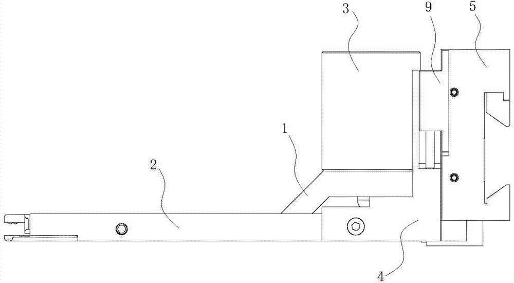
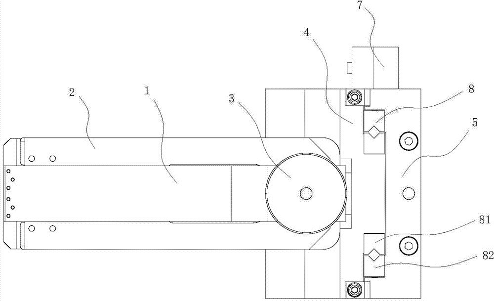
[0040] The present invention as Figure 1-9 As shown, it includes an upper pliers body 1, a lower pliers body 2 and a cylinder 3, the upper pliers body 1 and the lower pliers body 2 are hingedly connected, and the cylinder 3 is connected above the pliers tail end of the upper pliers body 1;

[0041] In the application, the standard cylinder with a longer stroke is used for the cylinder to avoid the problem of short stroke of the self-made cylinder. Due to the principle of force balance, under the premise of a certain air pressure, by moving the fulcrum of the upper and lower jaws forward, the clamping force on the jaws will be reduced. Increased holding power.

[0042] It also includes a base 4, a dovetail seat 5, a cylinder pad 6, a laser positioner 7, a pair of cross roller guide rails 8 and a pair of elastic guide mechanisms 9;

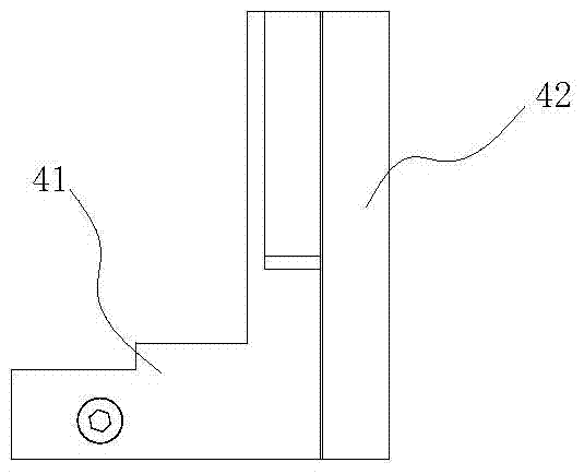
[0043] Such as Figure 3-6 As shown, the base 4 is L-shaped, including a connecting portion 41 at the front end and a guide portion 42 at th...


PUM


Abstract

The invention provides a split type board floating clamp on a numerical control press. The split type board floating clamp on the numerical control press is simple in structure, convenient to assemble, high in clamping reliability and capable of guaranteeing the position accuracy of a board. The split type board floating clamp on the numerical control press comprises an upper clamp body, a lower clamp body and an air cylinder. The upper clamp body is hinged to the lower clamp body. The split type board floating clamp further comprises a base, a dovetail base, an air cylinder cushion column, a laser locating device, a pair of intersecting roller guides and a pair of elastic guide mechanisms. The air cylinder cushion column is connected between the tail end of the upper clamp body and the tail end of the lower clamp body and used for being communicated with an air channel of the air cylinder. A first guide portion of the base and a second guide portion of the dovetail base maintain guiding operation in the perpendicular direction through the intersecting roller guides and are movably connected in the perpendicular direction through the elastic guide mechanisms. The laser locating device is fixedly connected to one side of the lower portion of the second guide portion of the dovetail base. According to the split type board floating clamp on the numerical control press, the board machining reliability is improved and the service life of a machine tool is prolonged.

Description

technical field [0001] The invention relates to the field of numerically controlled punching machines, in particular to a split-type plate floating clamp on a numerically controlled punching machine. Background technique [0002] At present, when the CNC punching machine is processing the plate, due to the high striking frequency and the large striking inertia, the plate will have a large jump, so the clamp is improved to a floating type; the applicant applied for the application on September 28, 2008 The number is 200820160567.5, and the name is "a floating clamping clamp on a CNC punching machine", which provides a floating connection between the cylinder body and the clamp base. Block), which is fixed on the beam of the CNC punching machine through the integral dovetail seat (connection of the clamp seat and the dovetail seat); There will be problems such as deformation of the plate locally. [0003] At the same time, in actual work, it often occurs that the sheet moves...

Claims


Application Information

Patent Timeline
IPC IPC(8): B21D43/00B21D28/02
Inventor 卞正文庄瑞斌韩林文家明秦赤球
Owner YANGZHOU HENGDE IND TECH CO LTD
Learn More