
Radiation detector comprising a circuit for injecting a calibrated quantity of counter-charges

A radiation detector and injection circuit technology, applied in the field of CMOS technology pixel array and array radiation detector, can solve problems affecting image quality and other issues

Inactive Publication Date: 2014-06-18
COMMISSARIAT A LENERGIE ATOMIQUE ET AUX ENERGIES ALTERNATIVES +1
View PDF2 Cites 6 Cited by
  • Summary
  • Abstract
  • Description
  • Claims
  • Application Information

AI Technical Summary

Problems solved by technology

This modification has a direct reaction to the estimation of the amount of photons received and thus affects the quality of the image obtained

Method used


Image

  • Radiation detector comprising a circuit for injecting a calibrated quantity of counter-charges
  • Radiation detector comprising a circuit for injecting a calibrated quantity of counter-charges
  • Radiation detector comprising a circuit for injecting a calibrated quantity of counter-charges

Examples


Embodiment Construction

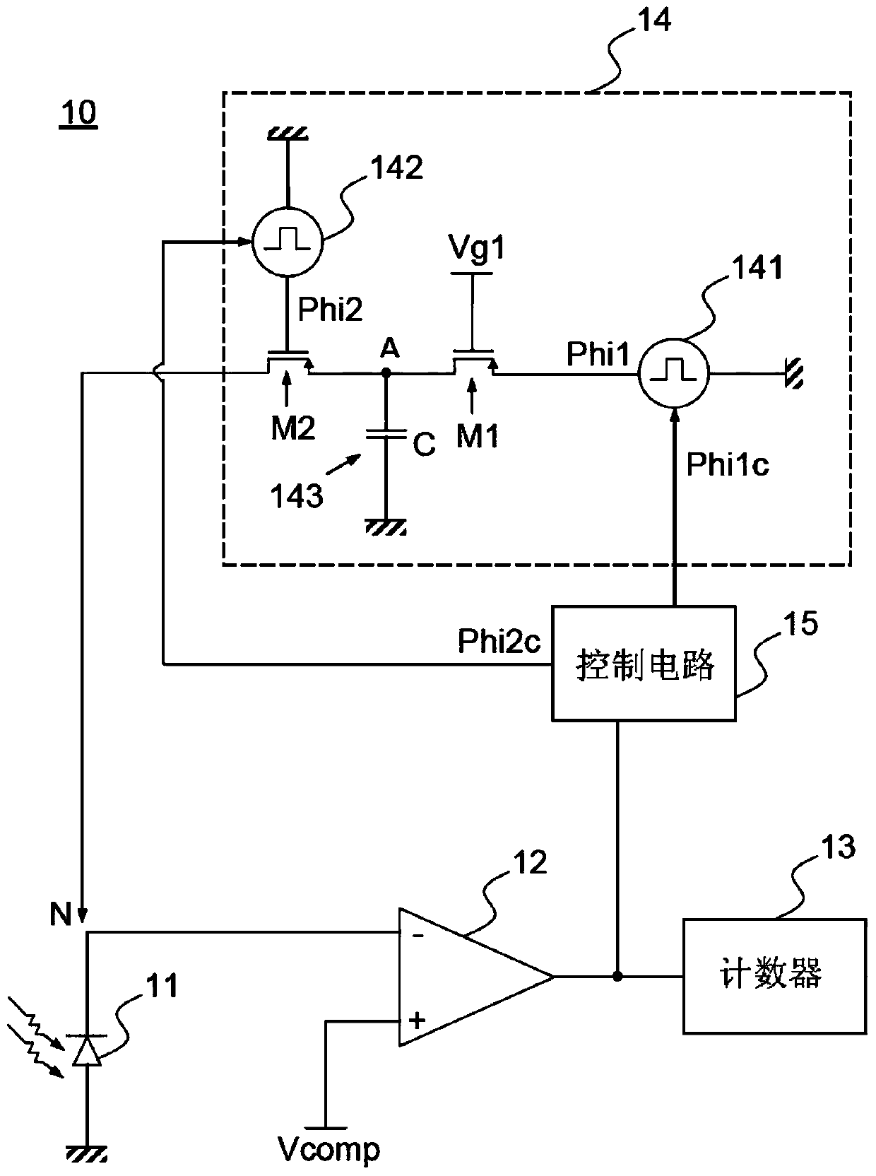
[0026] figure 1 A circuit diagram for a pixel 10 in an arrayed radiation detector according to the prior art is shown. Each pixel 10 forms a photosensitive spot in the array detector. The pixel 10 includes a photodiode 11 , a threshold comparator 12 , a counter 13 and a reverse charge injection circuit 14 . Threshold comparator 12 , counter 13 and injection circuit 14 form an electronic circuit allowing photodiode 11 to be read. Photodiode 11 may be replaced by a phototransistor, or, more generally, by any photosensitive element that generates a charge proportional to the amount of photons it receives. As an example, the photons under consideration have wavelengths in the visible domain or in the X-ray domain. In the case of the x-ray domain, the photosensitive element is directly charged under the influence of x-ray radiation or the photosensitive element is sensitive to visible radiation, in which case a scintillator is inserted between the x-ray source and the photosensi...


PUM


Abstract

The invention relates to an electronic circuit especially comprising: a comparator (12) receiving a threshold potential (Vcomp) and the potential of an integration node (N), said node being able to store electrical charges generated by a photosensitive element (11); a meter (13) connected at the outlet of the comparator (12); and a circuit (41) for injecting counter-charges. Said injection circuit comprises: a capacitor (143) storing counter-charges; a transfer transistor (M2) that can be controlled in the conducting state for transferring counter-charges from a terminal (A) of the capacitor (143) to the integration node (N) on every oscillation of the comparator (12), the transfer of the counter-charges triggering a variation of a potential (Va) at said terminal (A) of the capacitor (143); and a regulation circuit (42) for controlling the transfer transistor (M2), said regulation circuit comprising means (425) for controlling the transfer transistor (M2) in the conducting state when the potential at the terminal (A) of the capacitor (143) is between two pre-determined potentials (Vp2, Vcomp2) that are independent of the transfer transistor (M2).

Description

technical field [0001] The invention relates to electronic circuits for radiation detectors capable of quantifying radiation photons received by counter charge injection circuits. The invention relates in particular to an arrayed radiation detector for use in X-ray or gamma-ray imaging, comprising an array of CMOS technology pixels associated with a structure for converting X-rays or gamma-rays into electrical charges. Background technique [0002] An arrayed radiation detector includes an array of pixels and electronic circuitry forming a readout device. Each pixel includes a photosensitive element that generates a charge proportional to the amount of photons received. These charges, also known as photocharges, are processed by a reading device to provide a message representing the amount of photons received by each photosensitive element. The use of CMOS technology has allowed the integration of a reading device at each pixel. Thus, the charge can be converted into a di...

Claims


Application Information

Patent Timeline
Patent Type & Authority Applications(China)
IPC IPC(8): G01T1/24
CPCG01T1/247G01T1/24H01L27/14612H01L27/146G01T1/18G01T7/005
Inventor M·阿克斯
Owner COMMISSARIAT A LENERGIE ATOMIQUE ET AUX ENERGIES ALTERNATIVES
Learn More