MEMS piezoresistive resonator
A resonator and vibrator technology, applied in impedance networks, electrical components, etc., can solve problems such as poor frequency stability and affecting frequency stability
- Summary
- Abstract
- Description
- Claims
- Application Information
AI Technical Summary
Problems solved by technology
Method used
Image
Examples
Embodiment 1
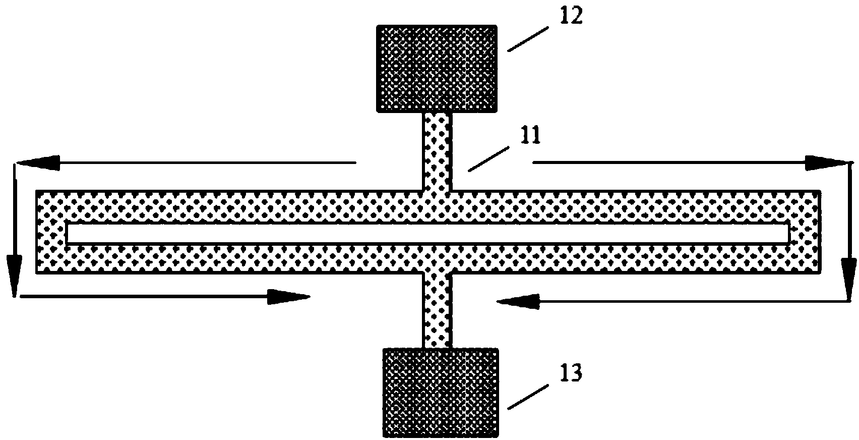
[0040]This embodiment provides a MEMS piezoresistive resonator, including: a substrate; at least a pair of input electrodes formed on the substrate, used to provide an AC voltage signal for the vibrator, so that the vibrator vibrates; an input bias a voltage electrode, formed on the substrate and located at the vibration node of the vibrator, for providing a DC bias voltage signal to the vibrator, so that the resistance of the vibrator responds to the change of the resistance of the vibrator caused by the AC voltage signal The generated sensing current flows through the vibrator; the output electrode is formed on the substrate and located at the node of vibration of the vibrator, and is arranged opposite to the input bias voltage electrode for responding to the sensing Measure the current, so as to output the frequency signal; the first anchor structure is used to support the vibrator on the input bias voltage electrode and transmit the DC bias voltage signal to the vibrator; t...
Embodiment 2
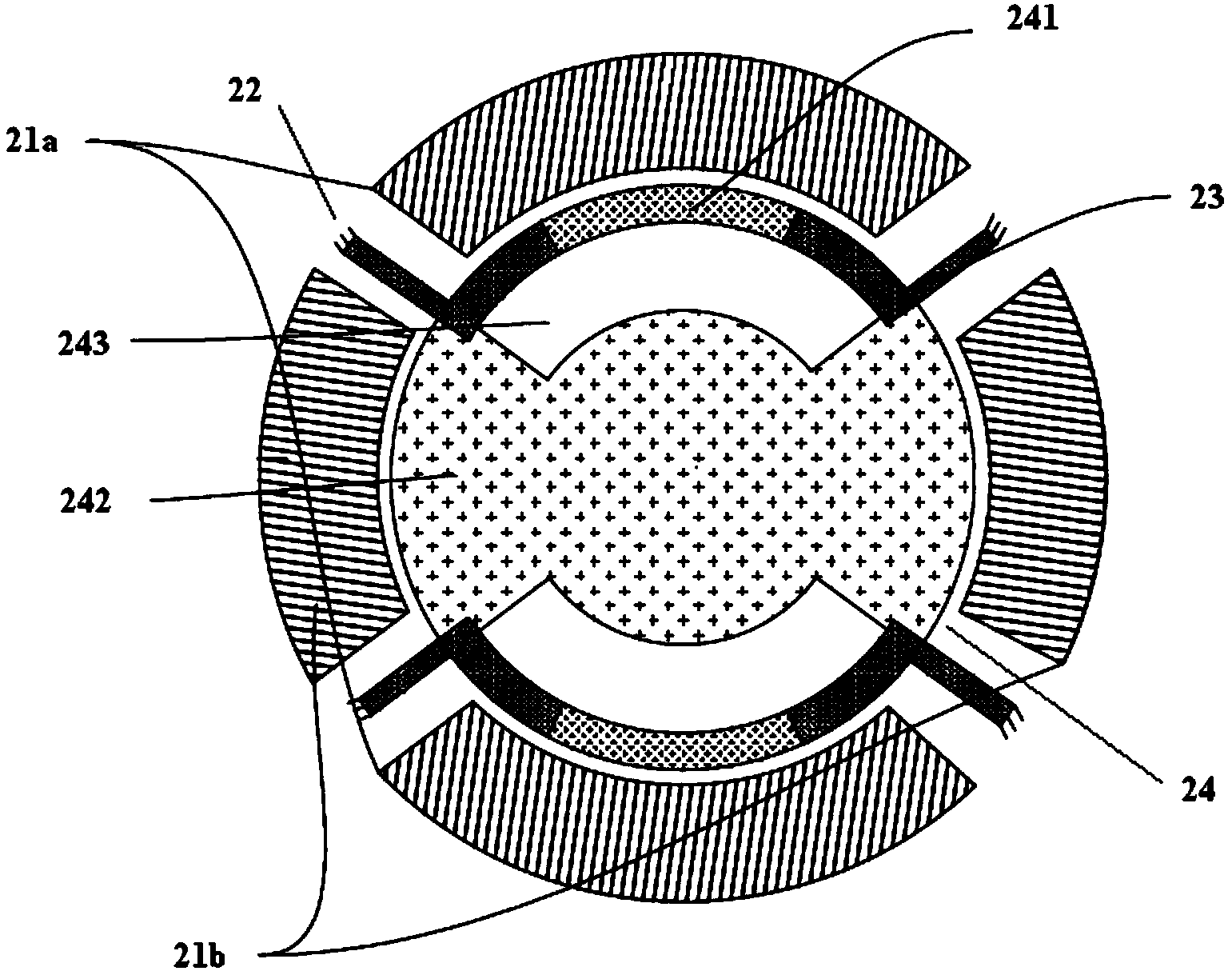
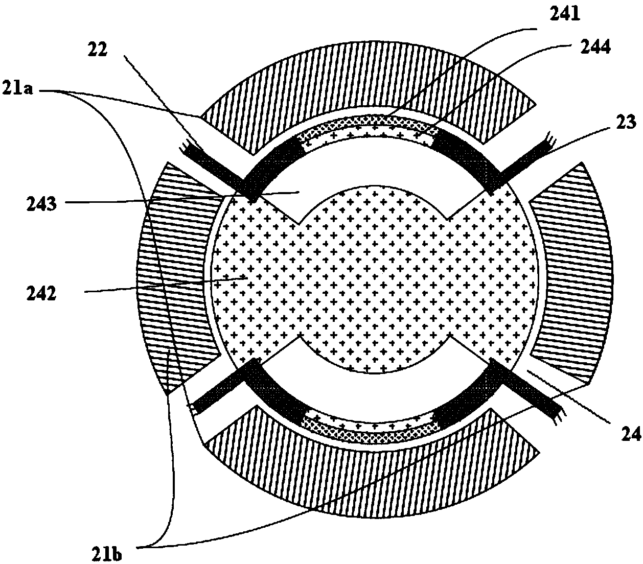
[0059] see figure 2 , is a schematic structural diagram of a MEMS piezoresistive resonator provided by an embodiment of the present invention. Such as figure 2 As shown, the resonator includes: a substrate, a first pair of input electrodes 21a, a second pair of input electrodes 21b, an input bias voltage electrode, an output electrode, a first anchor structure 22, a second anchor structure 23 and a vibrator 24, The vibrator 24 includes: a first region 241 through which the sensing current flows and a second region 242 through which the sensing current does not flow.
[0060] The similarities between this embodiment and the foregoing embodiment will not be repeated here. The difference is that the vibrator 24 further includes a hollowed out area 243 , and the hollowed out area 243 is located between the first area 241 and the second area 242 . The first pair of input electrodes 21a and the second pair of input electrodes 21b are evenly distributed in the circumferential di...
Embodiment 3
[0080] see Figure 7 , is a schematic structural diagram of another MEMS piezoresistive resonator provided by an embodiment of the present invention. Such as Figure 7 As shown, the resonator includes: a substrate, at least one pair of input electrodes, an input bias voltage electrode, an output electrode, a first anchor structure 72, a second anchor structure 73, and an oscillator 74, wherein the oscillator 74 includes: There is a first region 741 where the sensing current flows and a second region 742 where the sensing current does not flow. The vibrator 74 further includes a hollowed out area 743 located between the first area 741 and the second area 742 .
[0081] Optionally, the vibrator 74 has a symmetrical structure, wherein the hollowed out area 743 is a pair of symmetrical hollowed out areas, the second area 742 is located between the symmetrical hollowed out areas 743, and the first The area 741 is paired with the symmetrical hollow area 743 .
[0082] Further pr...
PUM
 Abstract
Description
Claims
Application Information
 - R&D
- Intellectual Property
- Life Sciences
- Materials
- Tech Scout
- Unparalleled Data Quality
- Higher Quality Content
- 60% Fewer Hallucinations
Browse by: Latest US Patents, China's latest patents, Technical Efficacy Thesaurus, Application Domain, Technology Topic, Popular Technical Reports.
© 2025 PatSnap. All rights reserved.Legal|Privacy policy|Modern Slavery Act Transparency Statement|Sitemap|About US| Contact US: help@patsnap.com


