
An injection molded sealed through-wall electrical connector

An electrical connector and wall-penetrating technology, which is applied in the field of injection-molded sealed wall-penetrating electrical connectors, can solve problems such as poor sealing, softening and leakage of adhesive glue or sintered materials, etc.

Active Publication Date: 2016-04-13
SUZHOU HUAZHAN SPACE APPLIANCE
View PDF6 Cites 0 Cited by
  • Summary
  • Abstract
  • Description
  • Claims
  • Application Information

AI Technical Summary

Problems solved by technology

[0004] At present, this series of connectors basically use ceramic sintering or glass sintering, bonding and other processes. In the sintering process, the linear expansion coefficients of the shell, inner conductor, and insulator are inconsistent, resulting in poor sealing and leakage. The reliability of bonding It is also low, and when it is in a high temperature, high temperature, and humid environment, the adhesive or sintered material will soften, making the connector loose or creating a gap between the inner wall of the housing and the insulator and the inner conductor, resulting in its sealing performance, Decreased insulation performance

Method used


Image

  • An injection molded sealed through-wall electrical connector
  • An injection molded sealed through-wall electrical connector
  • An injection molded sealed through-wall electrical connector

Examples


Embodiment Construction

[0021] The injection-molded sealed through-wall electrical connector of the present invention will be further described in detail in conjunction with the drawings and embodiments below:

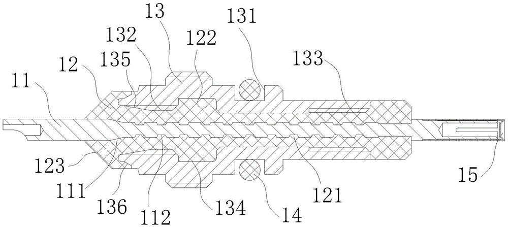
[0022] figure 1 Shown is a structural cross-sectional view of an embodiment of an injection-molded sealed through-wall electrical connector of the present invention. As shown in the figure, it includes a conductor contact 11 capable of transmitting current, surrounded by an injection molded insulator 12, and a metal shell 13 is arranged on the periphery of the above injection molded insulator 12, and a sealing ring 14 is arranged at the sealing groove 131 on it. . The inner seal is realized by the injection molding structure; the outer seal is realized by the compression deformation of the commonly used sealing ring 14, and the sealing ring 14 is made of elastic material, usually high temperature resistant fluororubber. The pressure-bearing end of the conductor contact 11 is provided with a...


PUM


Abstract

The invention discloses an injection molding sealing through-wall electric connector which comprises a conductor contact, an insulator, an outer shell and a sealing ring. The conductor contact is provided with the injection molding insulator in a surrounding mode, the metal outer shell is arranged on the periphery of the injection molding insulator, a sealing groove is formed in one side of the metal outer shell, the sealing ring is arranged in the sealing groove, and the conductor contact, the insulator and the metal outer shell are integrally combined through the injection molding process. The injection molding sealing through-wall electric connector is characterized in that the conductor contact is provided with a first conical surface tightly combined with the injection molding insulator, the pressure bearing end of the outer shell is provided with a second conical surface and a third conical surface which are tightly combined with the injection molding insulator, a cavity matched with a boss of the insulator is formed in the metal outer shell, meanwhile, the metal outer shell is provided with first internal threads and second internal threads, and the first internal threads and the second internal threads are used for preventing the insulator from rotating relative to the outer shell. By means of the injection molding sealing through-wall electric connector, the injection molding process and the pressure bearing structure are adopted, the good sealing performance and the good pressure bearing performance are achieved, and the injection molding sealing through-wall electric connector is suitable for electrical signal transmission occasions in severe environments with high pressure or high temperature and high pressure and the like.

Description

technical field [0001] The invention relates to the technical field of sealed connectors, in particular to an injection-molded sealed wall-through electrical connector that can be installed on a partition wall to withstand high temperature and high pressure on one side of the wall and normal pressure on the other side. Background technique [0002] Generally, in the fields of oil drilling and well logging, as well as subsea underwater detection operations, electronic equipment is often essential to realize functions such as transmission and analysis of electronic signals. The above-mentioned electronic equipment will encounter much higher pressure, or pressure and temperature, that is, harsh environments such as high pressure or high temperature and high pressure in the underground or on the seabed. In this environment, in order to ensure the reliable operation of electronic equipment, it must be placed in a closed container, and a through-wall connector is installed on the ...

Claims


Application Information

Patent Timeline
Patent Type & Authority Patents(China)
IPC IPC(8): H01R13/52H01R13/405H01R13/533H01R13/02
Inventor 罗宁
Owner SUZHOU HUAZHAN SPACE APPLIANCE
Learn More