
A Novel LTCC Double Layer Single Feed Circularly Polarized Microstrip Patch Array Antenna

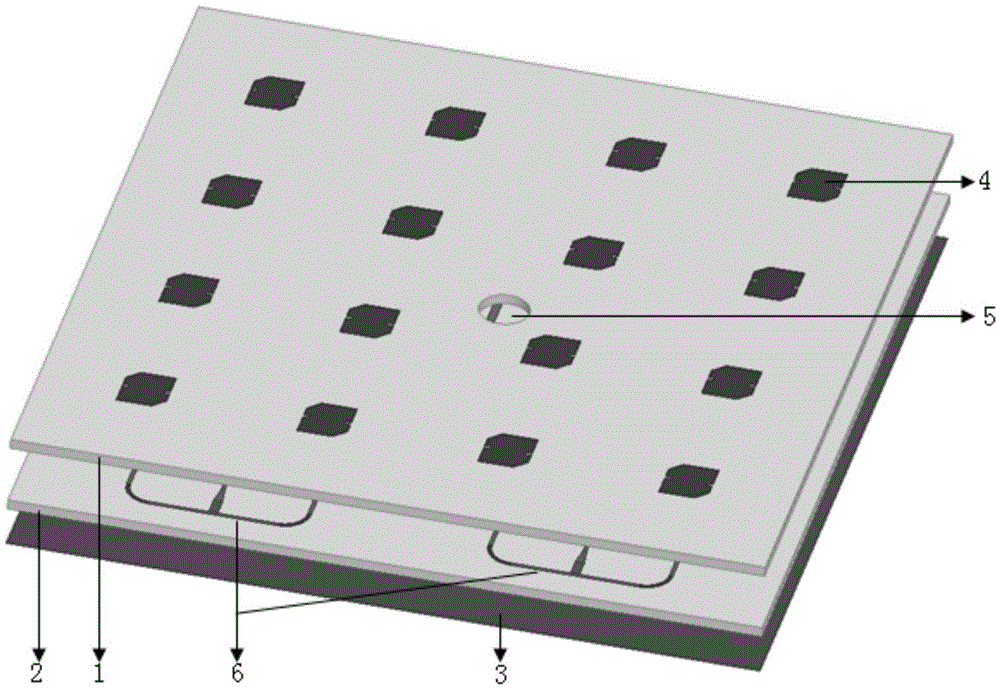
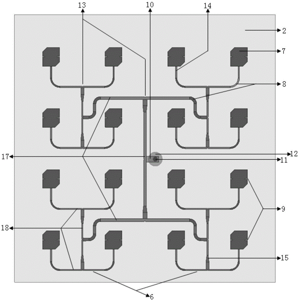
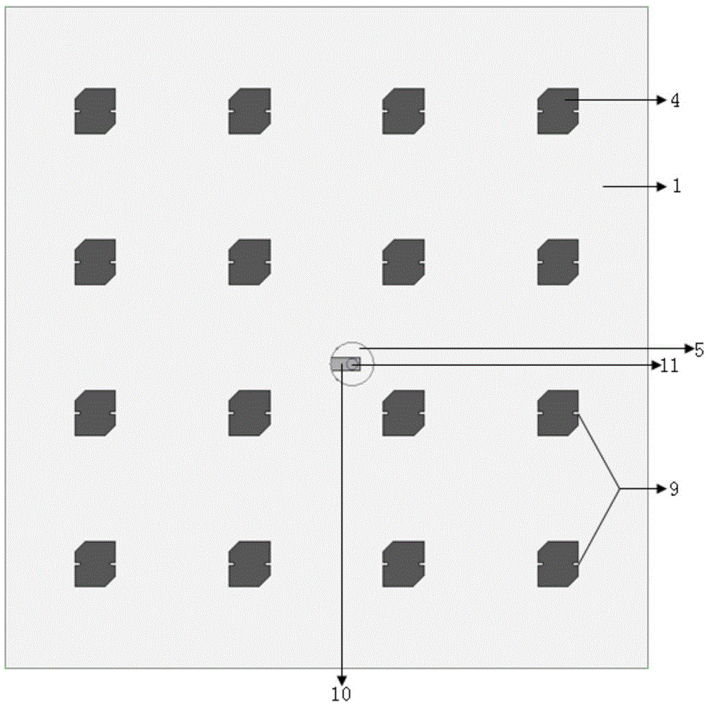
A technology of microstrip patch and array antenna, which is applied to antenna unit combinations, antennas, slot antennas and other directions with different polarization directions, which can solve the problem of high accuracy of chip cutting angle, increasing the complexity of antenna structure, and unfavorable antenna Miniaturization and other issues to achieve the effect of smaller size, simple structure and easy processing

Inactive Publication Date: 2016-05-18
UNIV OF ELECTRONICS SCI & TECH OF CHINA
View PDF2 Cites 0 Cited by
  • Summary
  • Abstract
  • Description
  • Claims
  • Application Information

AI Technical Summary

Problems solved by technology

At present, the common methods of widening the microstrip patch antenna include increasing the thickness of the substrate, adopting a multi-layer structure, and adding impedance matching, etc., but these are not only not conducive to the miniaturization of the antenna, but also make the antenna structure more complicated.
In addition, in realizing the circular polarization of the microstrip patch antenna, there are currently common methods of using multiple feeds and patch angle cutting, but the former increases the complexity of the antenna structure and reduces the gain of the antenna, and the latter has a negative impact on the antenna. Higher dimensional accuracy requirements for patch cut corners
The contradiction of circularly polarized microstrip patch array antenna taking into account its low profile, circular polarization, high gain, and broadband development has not been well resolved.

Method used


Image

  • A Novel LTCC Double Layer Single Feed Circularly Polarized Microstrip Patch Array Antenna
  • A Novel LTCC Double Layer Single Feed Circularly Polarized Microstrip Patch Array Antenna
  • A Novel LTCC Double Layer Single Feed Circularly Polarized Microstrip Patch Array Antenna

Examples


Embodiment Construction

[0028] The present invention will be further described in detail below with reference to the drawings and examples, but the embodiments of the present invention are not limited thereto.

[0029] The center frequency point of the microstrip patch array antenna provided in this embodiment is 10GHz, such as Figure 6 As shown, the present invention can realize a microstrip patch array antenna with an impedance bandwidth of 1.5 GHz and a maximum gain of more than 16.7 dB within a section thickness of 2 mm, and the axial ratio of the antenna can be less than 1.5 dB.

[0030] An LTCC double-layer single-feed circularly polarized microstrip patch array antenna provided in this embodiment includes:

[0031] Upper LTCC substrate 1: The substrate is laminated with 10 LTCC cast films with a thickness of 0.1mm and a dielectric constant of 5.9. The lateral dimension of the substrate is 74.2mm and the longitudinal dimension is 76.3mm. The upper surface of the substrate is printed with silv...


PUM


Abstract

The purpose of the present invention is to provide a double-layer single-feed circularly polarized microstrip patch array antenna based on LTCC technology, including upper and lower LTCC substrates, feeding networks, upper and lower radiation metal patch antenna arrays, and metal probes , a feed port and a grounded metal layer, wherein the lower radiating metal patch antenna array and the feeding network are located on the upper surface of the lower LTCC substrate, and the upper radiating metal patch antenna array is located on the upper surface of the upper LTCC substrate; the upper, The shape and size of the radiating metal patch antenna array in the lower layer are the same. Each antenna array is composed of four sub-arrays, and each sub-array is composed of four radiating metal patches. Each radiating metal patch is a square with a cut corner. Open rectangular gaps on opposite sides of the group. The antenna better takes into account the performance requirements of a microstrip patch antenna with low profile, circular polarization, and high gain, and at the same time greatly increases the frequency bandwidth of the antenna.

Description

technical field [0001] The invention belongs to the technical field of antennas, and in particular relates to a novel LTCC double-layer single-feed circularly polarized microstrip patch array antenna. Background technique [0002] Circularly polarized antennas are orthogonal in direction of rotation; incoming waves with any polarization can be received, and their radiated waves can also be received by antennas with any polarization; circularly polarized waves are incident on symmetrical targets, and the reflected waves are reverse-rotated. Compared with the array radiation unit, the array antenna has higher gain, narrower beam, stronger directivity and spatial beam scanning characteristics. The circularly polarized microstrip patch array antenna not only has the advantages of the above two antennas, but also has the advantages of low microstrip patch antenna profile, simple structure, small size, light weight, easy fabrication, low cost, and can be integrated with the carrie...

Claims


Application Information

Patent Timeline
Patent Type & Authority Patents(China)
IPC IPC(8): H01Q9/04H01Q13/08H01Q13/10H01Q21/24
Inventor 张怀武段耀铎郝欣欣
Owner UNIV OF ELECTRONICS SCI & TECH OF CHINA
Learn More