
Drum-type high-speed composite material rotor and manufacturing method thereof

A composite material, high-speed technology, applied in vibration suppression adjustment, textile, centrifuge, etc., can solve the problems of limiting the maximum operating frequency of the rotor, the axial helical lamination cannot be used, and the bending critical frequency of the axial stiffness drum is low.

Inactive Publication Date: 2016-02-10
TSINGHUA UNIV +1
View PDF7 Cites 0 Cited by
  • Summary
  • Abstract
  • Description
  • Claims
  • Application Information

AI Technical Summary

Problems solved by technology

The end of the hoop wound laminate is inserted between the sub-outer layer and the gap adjacent to the sub-outer layer and is handled by tension locking, but the axial helical laminate cannot be handled in a similar way
[0012] The fiber hoop-wound drum is perpendicular to the axial direction of the drum due to the high fiber stiffness direction, and the axial stiffness is completely provided by low-stiffness epoxy resin. The insufficient axial stiffness of the fiber hoop-wound rotor limits the increase in the length of the drum. The maximum operating frequency of the rotor is limited due to the low bending critical frequency of the long low axial stiffness rotor

Method used


Image

  • Drum-type high-speed composite material rotor and manufacturing method thereof
  • Drum-type high-speed composite material rotor and manufacturing method thereof
  • Drum-type high-speed composite material rotor and manufacturing method thereof

Examples


Embodiment Construction

[0081] The present invention will be further described below in conjunction with the embodiments and the accompanying drawings.

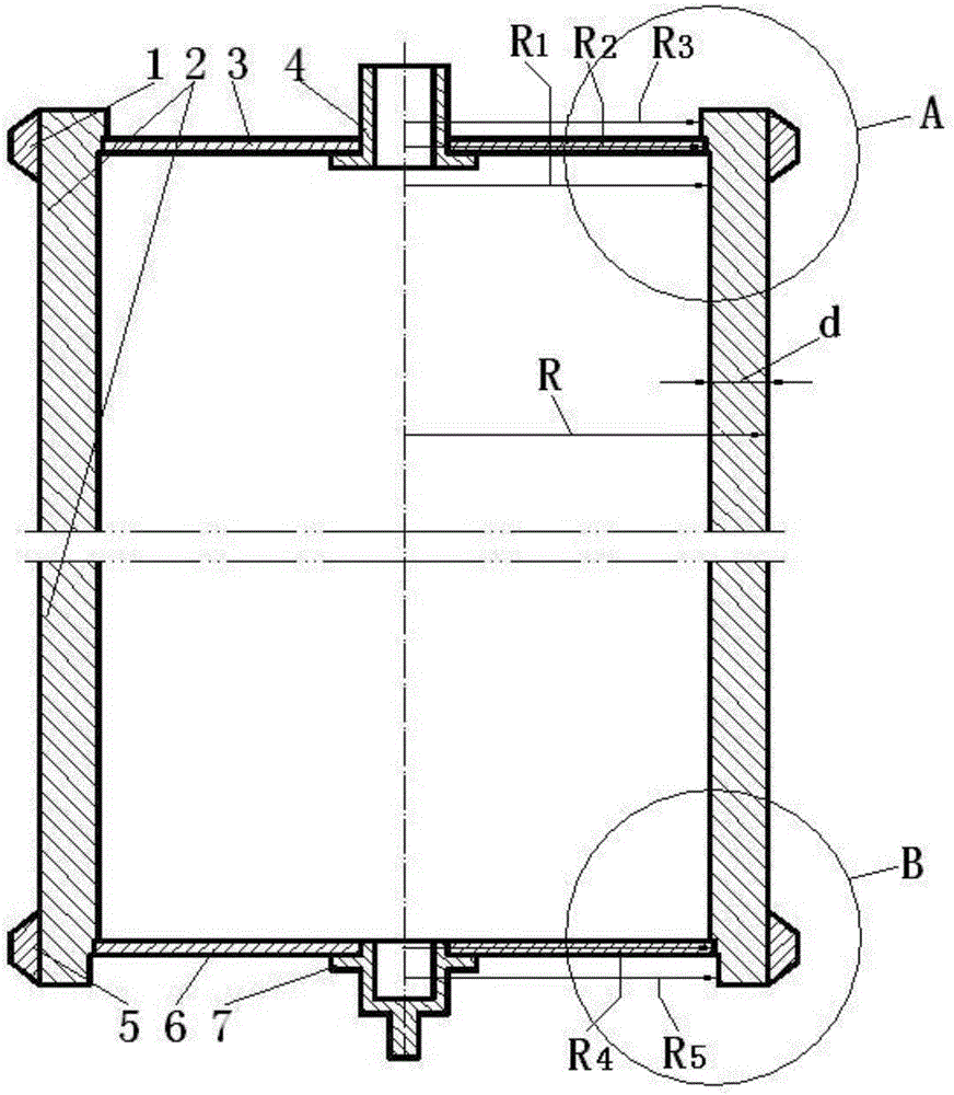
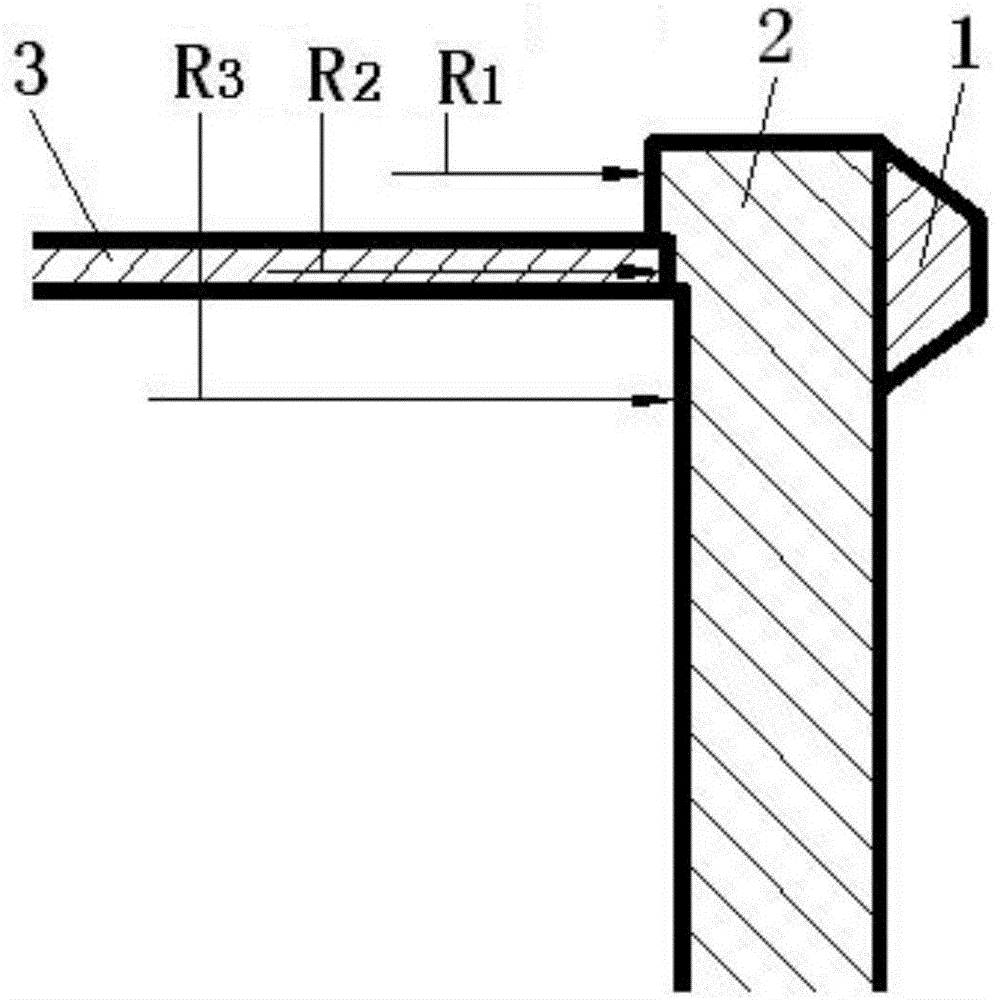
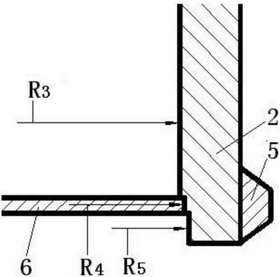
[0082] The structural schematic diagram of the drum-type high-speed composite material high-speed rotor embodiment is as follows figure 1 As shown, the drum-type high-speed composite material rotor includes an upper hoop 1, a cylinder body 2, an upper end cover 3, an upper tube shaft 4, a lower hoop 5, a lower end cap 6, and a lower mandrel 7, and each part is an axisymmetric structure. After assembly, they have a common central axis of rotation. The radius R of the outer wall of the cylinder 2 is 100mm, and the radius of the inner wall in the middle of the cylinder is R 3 , R and R 3 The difference, that is, the wall thickness d of the cylinder is 10mm, such as Figure 1A with Figure 1B As shown, the upper port and the lower port of the inner wall are stepped structures, from top to bottom, the radius of the inner wall of the upper port is R ...


PUM

PropertyMeasurementUnit
thicknessaaaaaaaaaa
diameteraaaaaaaaaa
diameteraaaaaaaaaa

Abstract

The invention belongs to the technical field of composite material structures, and in particular relates to a drum-type high-speed composite material rotor and a manufacturing method thereof. The drum-type high-speed composite material rotor includes an upper hoop, a cylinder body, an upper end cover, an upper tube shaft, a lower hoop, a lower end cover and a lower mandrel. The material of the cylinder wall is a composite material whose matrix is ​​epoxy resin. It is composed of hoop-wound fiber layers and axial fiber layers alternately, and the upper end cover and the lower end cover are both spiral fan-shaped texture laminates and composite material ring plates formed by composite molding with the matrix. The most important features of the present invention are: the cylinder body adopts carbon fiber unidirectional cloth as the axial stiffness reinforcement layer of the cylinder body, increasing the axial length of the drum; The texture adopts twill texture or twill / plain texture mixed texture, and the sewing reinforcement at the end of the spiral fan-shaped texture stack increases the structural stability of the textile texture prefabricated part. The invention is suitable for high-speed centrifuges or high-speed flywheels.

Description

technical field [0001] The invention belongs to the technical field of composite material structures, and in particular relates to a drum-type high-speed composite material rotor and a manufacturing method thereof. Background technique [0002] There are many small high-speed rotating machines in the industry: such as flywheel energy storage power supply units, centrifuges and turbomolecular pumps, etc. In order to bear the huge centrifugal stress when the rotor rotates at high speed, the rotor structure material generally adopts high specific strength (high strength, low density) Super duralumin, titanium alloy and fiber reinforced composite materials. [0003] The stress of the rotating structural parts increases according to the square relationship with the increase of the rotational speed. Due to the constraints of the strength and density of the metal material, the energy storage density of the flywheel is difficult to exceed 40Wh / kg, and the linear speed of the rotor o...

Claims


Application Information

Patent Timeline
Patent Type & Authority Patents(China)
IPC IPC(8): F16F15/305B04B7/08D03D15/00D03D13/00D03D15/275
Inventor 戴兴建张小章郭兴峰汪勇
Owner TSINGHUA UNIV
Learn More