U-shape Furnace Tube Bending Process Using Bending Roll Distance Sensor and Stress Relief Heat Treatment

A distance sensor, furnace tube bending technology, applied in manufacturing tools, metal processing equipment, feeding devices, etc., can solve the problems of low shape accuracy, long processing process, uneven processing deformation, etc., and achieve small processing space and bending process. continuous effect

Inactive Publication Date: 2015-09-09
扬州市金川表面处理有限公司
View PDF5 Cites 0 Cited by
  • Summary
  • Abstract
  • Description
  • Claims
  • Application Information

AI Technical Summary

Problems solved by technology

[0005] The invention is a U-shaped heating furnace tube bending process, which aims to solve the defects of uneven processing deformation, long processing process, and low shape precision in the prior art, and provides a bending process of a heating furnace tube with a specific shape. craft

Method used


Image

  • U-shape Furnace Tube Bending Process Using Bending Roll Distance Sensor and Stress Relief Heat Treatment
  • U-shape Furnace Tube Bending Process Using Bending Roll Distance Sensor and Stress Relief Heat Treatment
  • U-shape Furnace Tube Bending Process Using Bending Roll Distance Sensor and Stress Relief Heat Treatment

Examples


Embodiment Construction

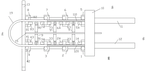
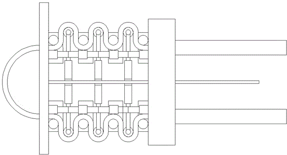
[0029] Attached below Figure 1-3 The present invention will be described in detail.

[0030] A U-shaped heating furnace tube bending process using a bending roller distance sensor and performing stress relief heat treatment, which uses a furnace tube bending device, the furnace tube bending device includes a left frame 13 and a pushing mechanism 10, pushing The mechanism 10 is on the right side of the left frame 13, and a guide rod 15 is fixed at the middle position on the right side of the left frame 13. The guide rod 15 extends horizontally in the left-right direction, and the left end of the guide rod 15 is connected to the left frame The frame 13 is fixedly connected, and the right end of the guide rod 15 is slidably connected to the middle of the pushing mechanism 10. The left frame 13 is provided with a raw U-shaped furnace tube for feeding through and for unloading the processed furnace tube. The passage through which the guide rod 15 slides from left to right between...


PUM


Abstract

Disclosed is a U-shaped heating furnace tube bending technology. According to the U-shaped heating furnace tube bending technology, furnace tube bending equipment is used, the furnace tube bending equipment comprises a left rack and a pushing mechanism, the pushing mechanism is arranged on the right side of the left rack, a guide rod is fixedly arranged in the middle part of the right side of the left rack, the guide rod extends horizontally in the left-right direction, the left end of the guide rod is fixedly connected with the left rack, the right end of the guide rod is connected with the middle of the pushing mechanism in a sliding mode, and a channel used for allowing an original U-shaped furnace tube to be fed and to penetrate through and a machined furnace tube to be discharged and to pass through is formed in the left rack; three bending hydraulic devices are sequentially arranged from left to right between the left rack and the pushing mechanism on the guide rod in a sliding mode.

Description

technical field [0001] The present application relates to the manufacture of a furnace tube of a heating furnace, in particular to a bending process of a furnace tube of a U-shaped heating furnace. Background technique [0002] Heating furnaces are widely used in industry, such as billet heating, workpiece heat treatment, etc. In order to increase the heating uniformity of the heating furnace, the furnace tube of the heating furnace often adopts a curved form. [0003] In the prior art, in order to ensure the requirements for the shape of the specific heating furnace and meet the requirements for the specific heating heat, it is usually necessary to bend the shape of the furnace tube to a specific shape. For the bending of the furnace tube of the heating furnace, stamping is often used in the prior art. This forming method can realize bending processing efficiently and quickly, has high processing precision and low cost, and is widely used in the prior art. However, this ...

Claims


Application Information

Patent Timeline
Patent Type & Authority Patents(China)
IPC IPC(8): B21D7/06B21D7/16B21D43/00
Inventor 汪贤女
Owner 扬州市金川表面处理有限公司
Why Eureka
Try Eureka