
Method and device for ensuring low-load and stable operation of gas discharger

A stable operation, low-load technology, applied in mechanical equipment, gas/liquid distribution and storage, pipeline systems, etc., can solve problems such as unfavorable production management, low user gas load, and increased equipment spare parts, etc. Management, reduction of production costs, and the effect of reducing the number of specifications

Active Publication Date: 2017-10-10
GUIYANG AL-MG DESIGN & RES INST
View PDF6 Cites 0 Cited by
  • Summary
  • Abstract
  • Description
  • Claims
  • Application Information

AI Technical Summary

Problems solved by technology

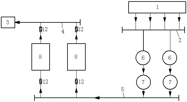
[0002]At present, in the gas supply system, the gas discharge unit used is composed of a group of gas discharge units with different discharge volumes. When the user's gas load is adjusted, when the user's gas load is large, more gas exhausters are used to supply gas; when the user's gas load is small, fewer gas exhausters are used to supply gas, but sometimes The user's gas load is very small. Even if only one gas delivery machine is used to supply gas to the user, the gas load of the gas user still does not meet the minimum gas delivery capacity of the gas delivery machine, and the safety of the user's use of gas cannot be guaranteed.
In order to ensure the stability of the gas pressure at the user end, only some gas dischargers with a small discharge volume can be installed in a group of gas dischargers, which results in a group of gas dischargers with various specifications of gas For the exhaust machine, if the gas consumption changes frequently, the gas exhaust machines of different specifications will also start and stop frequently, which will greatly increase the workload of the production and operation personnel. Increased spare parts, which are not conducive to production management

Method used


Image

  • Method and device for ensuring low-load and stable operation of gas discharger
  • Method and device for ensuring low-load and stable operation of gas discharger

Examples


Embodiment Construction

[0019] The present invention will be further described in detail below in conjunction with the accompanying drawings, but not as any limitation to the present invention.

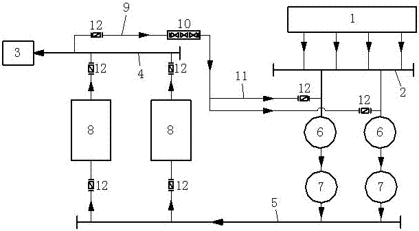
[0020] The method to ensure the stable operation of the gas discharge machine at low load, such as figure 1 shown. The method is to use a group of most commonly used gas dischargers with the same displacement to supply gas to users; to improve the interchangeability of equipment spare parts, reduce the specifications and quantities of equipment spare parts; and reduce the cost of equipment spare parts. When the gas load of the gas user is lower than the minimum gas discharge capacity of a group of gas dischargers, the excess gas is sent back to the intake main pipe or the inlet of the scrubber through the recirculation pipeline connected to the user main pipe, and the recirculation pipeline There is a pressure reducing valve; through the pressure reducing valve, the pressure in the main pipe of the user can...


PUM


Abstract

The invention discloses a method and device for ensuring the stable operation of a gas discharger with low load. The method is to use a group of gas dischargers to supply gas to users. When the gas delivery capacity is the lowest, the excess gas is returned to the intake main pipe or the scrubber inlet through the recirculation pipe connected to the user main pipe to ensure the normal operation of the gas discharge machine. In the present invention, by adding a recirculation pipeline between the user main pipe and the intake main pipe, the excess gas is returned to the intake main pipe or the inlet of the scrubber to reduce the pressure of the user main pipe and ensure that the gas pressure at the user end is maintained within a safe range. Since the present invention adopts the same specifications of the gas discharge machine, it can avoid the frequent start and stop of the gas discharge machines of different specifications, reduce the workload of the production and operation personnel, and also greatly reduce the specification and quantity of the spare parts of the equipment, which is beneficial to the production management, greatly reducing production costs.

Description

technical field [0001] The invention relates to a method and a device for ensuring the low-load and stable operation of a gas discharge machine, belonging to the technical field of gas supply. Background technique [0002] At present, in the gas supply system, the gas discharge unit used is composed of a group of gas discharge units with different discharge volumes. The operating number of the gas discharge units is adjusted according to the gas load of the user. When the user’s gas load is small, use a few less gas exhausters to supply gas, but sometimes the user’s gas load is very small, even if only one gas exhauster is turned on The machine supplies gas to the user, and the gas load of the gas user still does not meet the minimum gas delivery capacity of the gas delivery machine, which cannot guarantee the safety of the user in using gas. In order to ensure the stability of the gas pressure at the user end, only some gas dischargers with a small discharge volume can be ...

Claims


Application Information

Patent Timeline
Patent Type & Authority Patents(China)
IPC IPC(8): F17D1/04
Inventor 粟慧李忠军
Owner GUIYANG AL-MG DESIGN & RES INST
Learn More