
Rollover prevention system for two-wheeled vehicles

A technology of two-wheeled vehicles and rear wheels, which is applied in the field of rear wheel lifting devices, can solve problems such as increasing the risk of accidents, and achieve the effect of shortening the braking stroke

Inactive Publication Date: 2014-06-11
ROBERT BOSCH GMBH
View PDF3 Cites 1 Cited by
  • Summary
  • Abstract
  • Description
  • Claims
  • Application Information

AI Technical Summary

Problems solved by technology

This naturally increases the risk of accidents in so-called electric bicycles

Method used


Image

  • Rollover prevention system for two-wheeled vehicles

Examples


Embodiment Construction

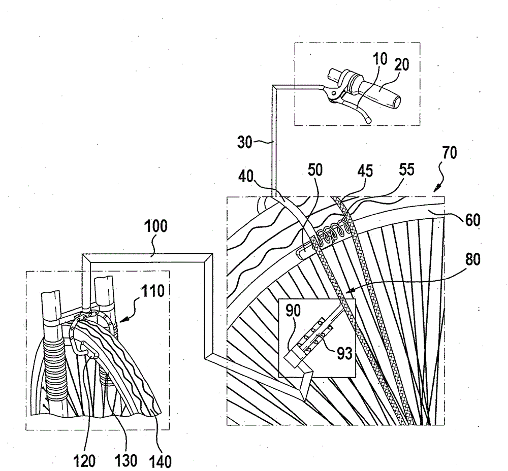
[0034] figure 1 A schematic diagram of an embodiment of a device for preventing the rear wheels of a two-wheeled vehicle from lifting off a roadway is shown.

[0035] If the brake lever 10 is pressed onto the handlebar 20 of the steering gear of the two-wheeler, the braking process is started in the two-wheeler. The brake 40 is activated via the brake line 30 . The brake 40 can here be a cable-pull brake or a hydraulic brake. exist figure 1 Hydraulic brakes are shown in .

[0036] Pressure builds up in brake lever 10 and transmits this pressure via hydraulic line 30 to brake shoe 50 . Subsequently, the brake shoe 50 is pressed onto the rim 60 of the rear wheel 70 . The bicycle is thus decelerated.

[0037] The rim brake 40 is engaged, and the pivot 80 fastened to the brake shoe is pressed to the left. In other words, the oscillator 80 then rotates to the left or counterclockwise.

[0038] A piston 93 of a hydraulic cylinder 90 is fixed to the oscillator 80 . If the hy...


PUM


Abstract

The present invention relates to a rollover prevention device for two-wheeled vehicles. The device has a vibrating unitthat is mounted rotatably on one side to a hub of a rear wheel of two-wheeled vehicle and is connected with a brake of the rear wheel. The device comprises at least a cylinder which is mounted on at least a vibration unit. The cylinder is connected with a brake of a front wheel of the two-wheeled vehicle through a pipeline. The device comprises at least a spring, which is mounted between the vibrating unit and a wheel suspension.

Description

technical field [0001] The present invention relates to a device for preventing the lifting of wheels, in particular a device for preventing the rear wheels of a two-wheeled vehicle from lifting. Background technique [0002] Simple two-wheeled vehicles such as bicycles are very popular. Due to the increasing demands placed on such two-wheeled vehicles, further improvements are always being made to them. In addition to purely human-powered mechanical two-wheelers, there are also more and more variants which are at least partially combined with an electric drive. An example of this is so-called electric bicycles (E-bikes). However, the invention can also be used in small motorized two-wheelers. [0003] An increased average speed of the two-wheeled vehicle can be achieved by various modifications. However, this also places higher and higher demands on the braking system. [0004] Brake systems which operate with disc brakes, drum brakes and rim brakes, which are cable-dr...

Claims


Application Information

Patent Timeline
Patent Type & Authority Applications(China)
IPC IPC(8): B62J27/00B62L1/00
CPCB62L3/08B62L3/023B60T8/261B60T8/52
Inventor A.弗哈根C.莫辰巴赫尔
Owner ROBERT BOSCH GMBH
Learn More