Structure of thermal protective coating for launching pad and application of structure

A technology for thermal protection and launching pads, which is applied in the direction of coating, layered products, metal layered products, etc. It can solve the problems of heavy weight, thick thickness, and the inability of the launching pad to move, so as to reduce thermal ablation and thermal shock Effect

Active Publication Date: 2014-06-11
DALIAN INST OF CHEM PHYSICS CHINESE ACAD OF SCI
View PDF4 Cites 8 Cited by
  • Summary
  • Abstract
  • Description
  • Claims
  • Application Information

AI Technical Summary

Problems solved by technology

In foreign countries, the Ariane rocket launch platform of the European Space Agency in Guyana, South America is a concrete launch platform. This type of launch platform constructed of inorganic non-metallic materials has better gas purging and ablation resistance than organic ablation coatings, but th...

Method used


Image

  • Structure of thermal protective coating for launching pad and application of structure
  • Structure of thermal protective coating for launching pad and application of structure
  • Structure of thermal protective coating for launching pad and application of structure

Examples


Embodiment 1

[0018] The preparation of embodiment 1 thermal protective coating structure

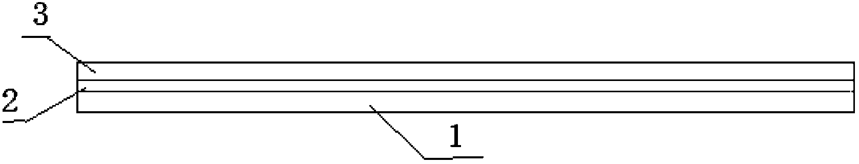
[0019] 1. Preparation of organic bottom layer: mix epoxy resin SM828, curing agent polyamide 650, and toughening agent liquid rubber in a ratio of 7:2:1, and then coat it on the 190×120×5mm surface after removing rust and paint. On the steel plate, the coating thickness is 2mm.

[0020] 2. Preparation of organic-inorganic composite surface layer: First, mix the filler sand and cement evenly in a ratio of 2:1, and then add it to the mixed glue of organic adhesive epoxy resin SM815 and polyurethane curing agent 735 in a ratio of 3:1, solid The ratio to liquid is 3:1. Before the organic bottom layer is fully cured, the surface layer material is coated on the bottom layer material. A surface layer with a thickness of 4 mm is coated on a base layer with a thickness of 2 mm to prepare a thermal protection coating with a total thickness of 6 mm.

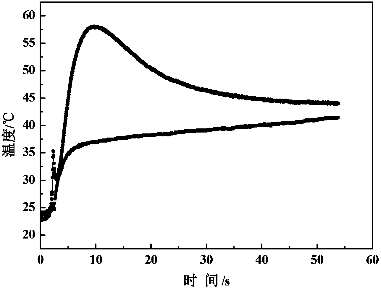
[0021] Tests on the thermal protection effect of heat-pro...

Embodiment 2

[0023] The preparation of embodiment 2 thermal protection coating structure

[0024] 1. Preparation of organic bottom layer: mix epoxy resin SM828, curing agent polyamide 650, and toughening agent liquid rubber in a ratio of 7:2:1, and then coat it on the 190×120×5mm surface after removing rust and paint. On the steel plate, the coating thickness is 4mm.

[0025] 2. Preparation of organic-inorganic composite surface layer: First, mix the filler sand and cement evenly in a ratio of 2:1, and then add it to the mixed glue of organic adhesive epoxy resin SM815 and polyurethane curing agent 735 in a ratio of 3:1, solid The ratio to liquid is 3:1. Before the organic bottom layer is fully cured, the surface layer material is coated on the bottom layer material. A surface layer with a thickness of 11 mm is coated on a base layer with a thickness of 4 mm to prepare a thermal protection coating with a total thickness of 15 mm.

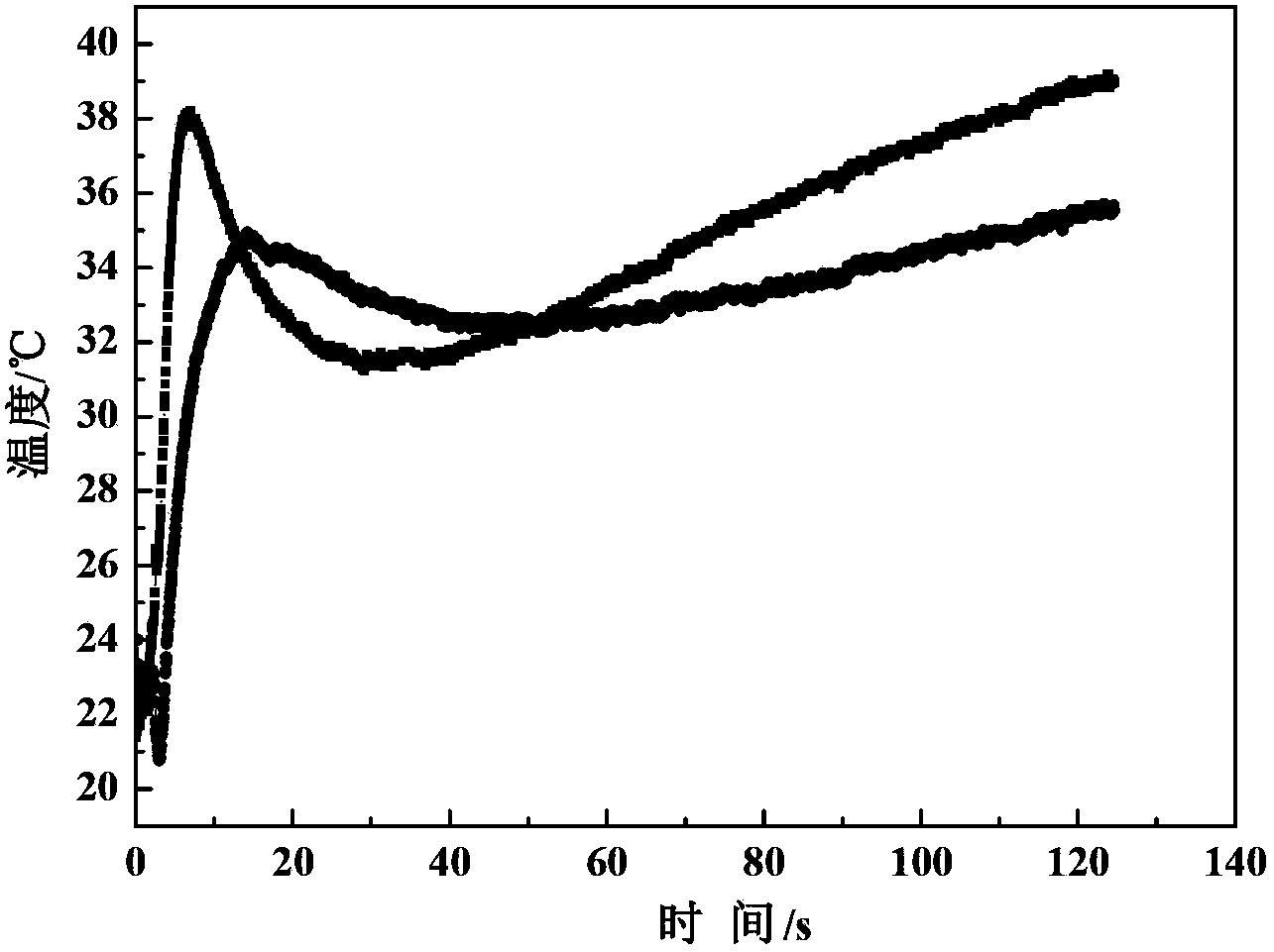
[0026] Tests on the thermal protection effect of the th...


PUM


Abstract

The invention discloses a structure of a thermal protective coating for a launching pad and an application of the structure. The thermal protective coating material comprises an organic base layer and an organic-inorganic composite surface layer, wherein the organic base layer comprises epoxy resin, polyamide as a curing agent and liquid rubber as a toughening agent; the organic-inorganic composite surface layer comprises organic glue epoxy resin, a polyurethane curing agent, sand and cement. The thermal protective coating material can bear the simulated combustion gas flow scouring of a rocket, the temperature of a metal back surface does not exceed 200 DEG C, and the coating has excellent thermal insulation property.

Description

technical field [0001] The invention relates to a heat protection coating structure of a rocket launch pad, in particular to a heat protection coating structure for coating the surface of a rocket launch pad to reduce the back temperature of the launch pad and an application thereof, which belongs to the field of high temperature resistance and heat insulation protection. Background technique [0002] With the development of aerospace and aerospace industry, thermal protective coatings have opened up new application fields. In addition to the thermal protection of the aircraft itself, thermal protection measures have also been added to ground facilities such as rocket launch pads in China. If the launch pad is coated with thermal protective coatings, it can insulate the metal surface, reduce thermal ablation and thermal shock, and prevent the launch pad from thermal fatigue, thermal cracking and thermal fracture under multiple thermal shock loads, thereby ensuring The relia...

Claims


Application Information

Patent Timeline
IPC IPC(8): B32B27/06B32B27/20B32B27/38B32B15/092B32B33/00C09D163/00C09D7/12
Inventor 马磊张巍臧红王国鹏张涛
Owner DALIAN INST OF CHEM PHYSICS CHINESE ACAD OF SCI
Why Eureka
Try Eureka