
Polishing machine with improved adsorption method for polished parts

A polishing machine and adsorption tank technology, applied in the field of polishing machines, can solve problems such as poor air tightness, increased equipment costs, and increased costs, and achieve simplified adsorption and peeling processes, easy adhesion and peeling, and easy loading and unloading The effect of taking the film

Active Publication Date: 2016-06-29
湖南永创机电设备有限公司
View PDF6 Cites 0 Cited by
  • Summary
  • Abstract
  • Description
  • Claims
  • Application Information

AI Technical Summary

Problems solved by technology

After a period of use, the polishing powder will gradually penetrate into the small holes on the front of the adsorption pad, so that the original small holes cannot be used without vacuum adsorption function, and must be replaced frequently
Calculated by the polishing machine working eight hours a day, the adsorption pad of polyester synthetic material has to be replaced every few days, which leads to the high cost of the adsorption pad of polyester synthetic material as a consumable for polishing.
[0003] In addition, the polishing machine needs to peel off the adsorption pad adsorbed on the glass after processing each piece of glass. According to the existing technology, it can only be removed by manual air blowing or water seepage, which is quite time-consuming and laborious, and affects the entire polishing machine. degree of automation
In the prior art, there is also a method of vacuum adsorption connecting the upper plate of the polishing machine to a ceramic moving plate, but the setting of the ceramic moving plate not only increases the equipment cost, but also the quality of the ceramic moving plate is relatively heavy, and the polishing required The power consumption is greatly increased. It is time-consuming and labor-intensive to place the polished wafer on the ceramic moving plate, and this hard contact is easy to cause damage to the wafer during polishing, and the polishing quality cannot be guaranteed. In the prior art, there are also vacuum chucks with holes to directly absorb the workpiece However, this vacuum adsorption method often has poor airtightness, which leads to excessive adsorption pressure required for vacuum adsorption, which not only easily causes deformation of the workpiece and affects the polishing accuracy, but also easily causes damage to the workpiece, and the polishing powder If other impurities enter the pores on the vacuum suction cup, it is not only difficult to clean up, but in severe cases, the entire vacuum suction cup needs to be replaced, and the cost will increase greatly

Method used


Image

  • Polishing machine with improved adsorption method for polished parts
  • Polishing machine with improved adsorption method for polished parts
  • Polishing machine with improved adsorption method for polished parts

Examples


Embodiment 1

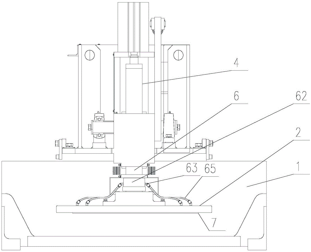
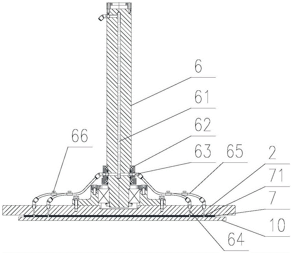
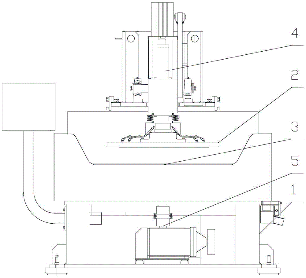
[0033] a kind of like Figure 1 ~ Figure 3 The up-suction polishing machine of the present invention, which improves the adsorption mode of polishing parts, includes a frame 1, an adsorption upper plate 2, an adsorption lower plate 3, an upper plate drive system 4, a lower plate drive system 5, a recovery system and a vacuum system , the upper disk drive system 4 includes a central shaft 6, the bottom of the central shaft 6 is connected with the adsorption upper disk 2, a closed connection air circuit 61 is opened in the central shaft 6, and a rotary air circuit joint is provided near the bottom of the central shaft 6 62. The inner end of the rotary gas path connector 62 is connected to the external vacuum system through the closed connection gas path 61 (conventional vacuum system can be used, not shown in the figure), and the outer end of the rotary gas path connector 62 is set There are a plurality of air passage interfaces 63, and the adsorption upper plate 2 is provided w...

Embodiment 2

[0039] a kind of like Figure 4 ~ Figure 7 The down-suction polishing machine of the present invention, which improves the adsorption method of polishing parts, includes a frame 1, an adsorption upper plate 2, an adsorption lower plate 3, an upper plate drive system 4, a lower plate drive system 5, a recovery system and a vacuum system (see Figure 7 ), the lower disc drive system 5 includes a central shaft 6, the top of the central shaft 6 is connected with the adsorption lower disc 3, the central shaft 6 is provided with a closed connection air circuit 61, and the central shaft 6 is provided with a rotating air circuit near the bottom Joint 62, the upper end of the rotary air path joint 62 is connected with the bottom end of the closed connection air path 61, the lower end of the rotary air path joint 62 is connected with the vacuum system, and the upper part of the closed connection air path 61 is connected to the outside of the central axis 6. The air path interface 63 of...


PUM


Abstract

The invention discloses a polishing machine with an improved polished piece adsorption mode. The polishing machine comprises a machine frame, an adsorption upper disk, an adsorption lower disk, an upper disk drive system, a lower disk drive system and a vacuumizing system, wherein the upper / lower disk drive system comprises a central shaft; the bottom of the central shaft is connected with the adsorption upper / lower disk; a closed connecting air channel is formed in the central shaft; a rotary air channel connector is arranged at the position, close to the bottom, of the central shaft; the rotary air channel connector is communicated to the closed connecting air channel; air channel connecting openings are formed in the outer end of the rotary air channel connector; air channel through holes are formed in the adsorption upper / lower disk; the air channel connecting openings are communicated with the air channel through holes formed in the adsorption upper / lower disk through connecting air pipes; a cushion pad which is closely adhered to the lower surface of the adsorption upper / lower disk is arranged below / above the adsorption upper / lower disk; a through-type adsorption groove is formed in the surface of each cushion pad; the lower / upper end of each air channel through hole is flush with the corresponding adsorption groove. The polishing machine with the improved polished piece adsorption mode is simple in structure, low in cost, low in investment and convenient to operate, and facilities later-period automatic polishing.

Description

technical field [0001] The invention relates to a polishing machine, in particular to a polishing machine which improves the adsorption mode of polishing parts. Background technique [0002] At present, the glass processed by the polishing machine is attached to the plane of the upper or lower disc of the polishing machine for processing, and the adsorption pad of polyester synthetic material is adsorbed on the plane of the upper and lower discs for grinding and polishing. Most of the upper and lower plates of the existing polishing machines are flat and non-porous structures, and they do not have the function of vacuum adsorption. These polishing machines mainly rely on the adsorption pads of special materials to complete the bonding and fixing of the glass to be polished. , adhesives, etc. are bonded to the upper and lower plates, and the front of the adsorption pad is composed of many fine groove-shaped small holes. After pressing tightly, the air in the small holes is di...

Claims


Application Information

Patent Timeline
Patent Type & Authority Patents(China)
IPC IPC(8): B24B37/30
CPCB24B37/28
Inventor 汪兴刘亚彪杨会义刘仲宁周继国李新良
Owner 湖南永创机电设备有限公司
Learn More