
Anti-reverse paddleless mixer

A mixer, anti-reverse technology, applied in mixers with rotating containers, mixers, dissolving and other directions, can solve problems such as reverse swing, and achieve the effect of high speed control accuracy and hard torque characteristics

Active Publication Date: 2016-04-13
SHANGHAI AEROSPACE CHEM ENG INST
View PDF2 Cites 0 Cited by
  • Summary
  • Abstract
  • Description
  • Claims
  • Application Information

AI Technical Summary

Problems solved by technology

[0003] The purpose of the present invention is to provide an anti-reverse paddleless mixer, which solves the reverse swing phenomenon caused by the inertial impact of the slurry during the positioning process of the paddleless mixer

Method used


Image

  • Anti-reverse paddleless mixer
  • Anti-reverse paddleless mixer

Examples


Embodiment Construction

[0020] In order to make the above objects, features and advantages of the present invention more obvious and comprehensible, specific implementations of the present invention will be described in detail below in conjunction with the accompanying drawings and embodiments.

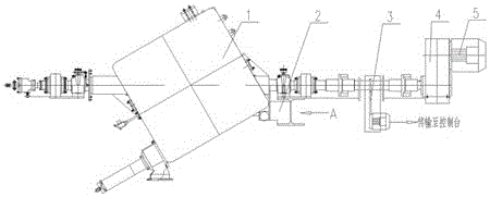
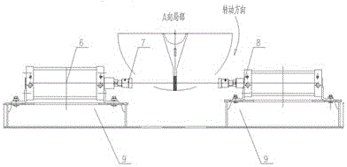
[0021] refer to figure 1 and figure 2 , the power device of the main equipment 1 of the paddleless mixer in this embodiment is a DC motor 5 , and the DC motor 5 is equipped with a one-way anti-reverse reducer 4 . The DC motor 5 has the ability of stepless speed regulation, and has the characteristics of hard torque characteristics and high speed control precision. By cooperating with the one-way anti-reverse reducer 4, it solves the problem of the paddleless mixer due to The inertial impact of the slurry produces a reverse swing phenomenon.

[0022] Preferably, in this embodiment, the operating speed of the main equipment 1 is 0.5-20 rpm, and the use of different operating speeds at different stages of pr...


PUM


Abstract

An anti-reversal paddleless mixer, the power device of the main equipment of the paddleless mixer is a DC motor, and the DC motor is equipped with a one-way anti-reverse reducer. The invention solves the reverse swing phenomenon caused by the inertial impact of the slurry during the positioning process of the paddleless mixer.

Description

technical field [0001] The invention relates to an anti-reverse paddleless mixer. Background technique [0002] In the prior art, the power device of the paddleless mixer is two three-phase asynchronous motors, and the speed of the paddleless mixer is 10 rpm (normal mixing operation) and 1 rpm (stop positioning) through the reducer. The clamping and positioning mechanism adopts standard cylinders with the same inner diameter and stroke, which are symmetrically arranged on both sides of the predetermined position, and are synchronized with each other in action execution control. During the positioning process, the propellant slurry has a certain impact on the mixing container due to inertia, and the cylinder swings left and right within a certain angle range at the predetermined position. When positioning and clamping, it takes a certain period of time for the cylinder to shut down before it can be executed. At the same time, due to the different mixing stages of the propell...

Claims


Application Information

Patent Timeline
Patent Type & Authority Patents(China)
IPC IPC(8): B01F9/04B01F29/62
Inventor 袁睿斌张晖
Owner SHANGHAI AEROSPACE CHEM ENG INST
Learn More