
Carbon fiber tube

A technology of carbon fiber tube and carbon fiber, which is applied in the direction of layered products, chemical instruments and methods, metal layered products, etc., can solve the problems of general reinforcement effect and single structure, and achieve the effect of good reinforcement effect, increased strength and convenient processing

Inactive Publication Date: 2014-06-04
昆山盛夏复合材料科技有限公司
View PDF6 Cites 3 Cited by
  • Summary
  • Abstract
  • Description
  • Claims
  • Application Information

AI Technical Summary

Problems solved by technology

However, in the current carbon fiber tubes, the ribs are mostly parallel to the axis, the structure is single, and the reinforcing effect is general.

Method used


Image

  • Carbon fiber tube
  • Carbon fiber tube

Examples


Embodiment Construction

[0016] The present invention will be specifically introduced below in conjunction with the accompanying drawings and specific embodiments.

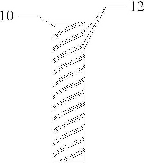
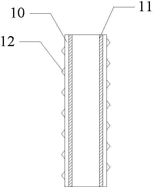
[0017] Such as figure 1 , figure 2 The shown carbon fiber tube includes a cylindrical tube body 10, the tube body 10 is a carbon fiber tube body, the inner side of the tube body 10 is provided with a metal inner wall 11, and the outer side of the tube body 10 is provided with a plurality of helical reinforcing ribs 12, many The helical reinforcing ribs are parallel to each other, and each helical reinforcing rib 12 is evenly distributed, and the distance between each helical reinforcing rib 12 is equal to 1.5 to 2 times the helical reinforcing rib 12 and the pipe body. 10 Width at contact. The metal inner wall 11 adopts an aluminum tube to closely fit the carbon fiber tube body. The aluminum is lightweight, and the carbon fiber tubes on the outside add strength.

[0018] The helix angle of the helical reinforcing rib 12 is 45°-60°. ...


PUM

PropertyMeasurementUnit
angleaaaaaaaaaa

Abstract

The invention discloses a carbon fiber tube. The carbon fiber tube comprises a cylindrical tube body. The carbon fiber tube is characterized in that the tube body is a carbon fiber tube body, wherein a metal inner wall is arranged on the inner side of the tube body, a plurality of spiral-line reinforcing ribs are arranged on the outer side of the tube body, are parallel with one another and are equidistantly and uniformly distributed. The carbon fiber tube has the beneficial effects that the strengthening effects of the spiral-line reinforcing ribs are better than the strengthening effect of a linear reinforcing rib, so that the strength of the carbon fiber tube is improved; the reinforcing ribs with triangular cross sections can play reinforcing effects, the material is saved, and meanwhile, the machining is facilitated.

Description

technical field [0001] The invention relates to a composite material pipe, in particular to a carbon fiber pipe. Background technique [0002] Carbon fiber has the characteristics of high strength, high modulus, high temperature resistance, corrosion resistance, fatigue resistance, creep resistance, electrical conductivity, and heat transfer, and is a typical high-tech product. It has been widely used in the field of aerospace, sporting goods, industry, transportation and civil engineering. [0003] At present, carbon fiber tubes are widely used to replace metal tubes in machining to achieve the purpose of reducing the weight of the machine itself and improving the strength. However, in the current carbon fiber tubes, most of the ribs are parallel to the axis, the structure is single, and the reinforcing effect is average. Contents of the invention [0004] In order to solve the deficiencies of the prior art, the purpose of the present invention is to provide a carbon fi...

Claims


Application Information

Patent Timeline
Patent Type & Authority Applications(China)
IPC IPC(8): B32B1/08B32B15/04B32B15/14
Inventor 陆建萍
Owner 昆山盛夏复合材料科技有限公司
Learn More