
Micro-fluidic chip for multi-index detection

A microfluidic chip and multi-indicator technology, applied in fluid controllers, laboratory containers, microbial measurement/inspection, etc., can solve the problem of air bubbles in the main channel, cannot ensure that the liquid is always filled with the sample hole, and increase chip manufacturing issues of complexity

Active Publication Date: 2014-06-04
BOAO BIOLOGICAL CO LTD +1
View PDF6 Cites 48 Cited by
  • Summary
  • Abstract
  • Description
  • Claims
  • Application Information

AI Technical Summary

Problems solved by technology

The design of the main channel, that is, the design of the main channel with the same width between the mountain and the valley still fails to solve the problem of the uniformity of liquid dosing in each sampling hole; in addition, the design of the valley is too wide than the mountain, resulting in There is a problem of air bubbles in the main flow
In addition, by adding the waste liquid chamber to carry excess solution, although the consistency of the liquid volume distributed in each sample hole is achieved to a certain extent, it cannot guarantee that the liquid is always full of the sample hole during the reaction process, and it needs to be filled in the microfluidic pipeline. Local surface modification treatment is carried out inside, that is, the hydrophilic treatment of the inner surface of the branch flow channel connected to the sample hole, and the hydrophobic treatment of the inner surface of the branch flow channel connected with the waste liquid chamber that collects the remaining solution, which increases the complexity of chip manufacturing. Sex, processing cost and processing difficulty

Method used


Image

  • Micro-fluidic chip for multi-index detection
  • Micro-fluidic chip for multi-index detection
  • Micro-fluidic chip for multi-index detection

Examples


Embodiment Construction

[0046] The present invention will be further described below in conjunction with the drawings, but the present invention is not limited to the following embodiments.

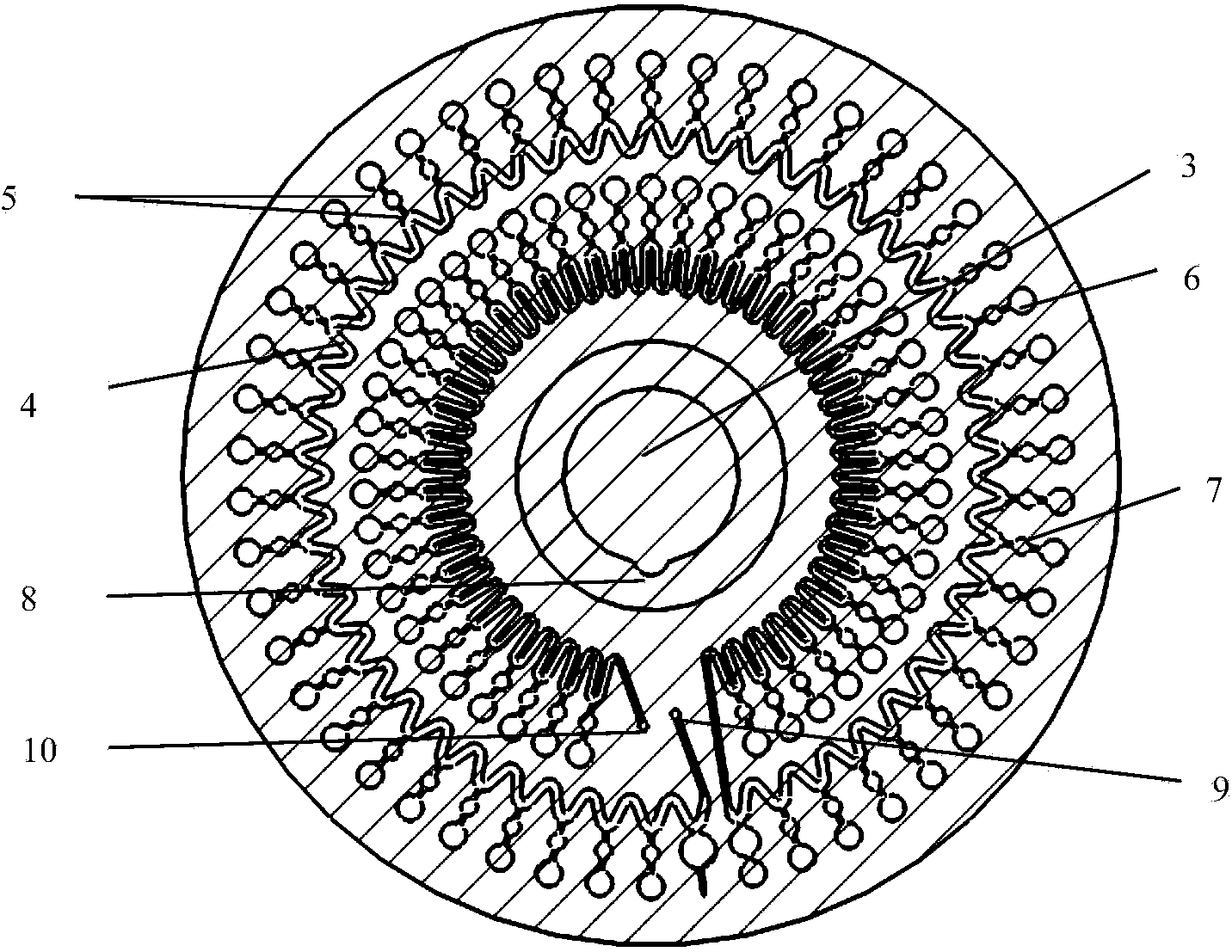
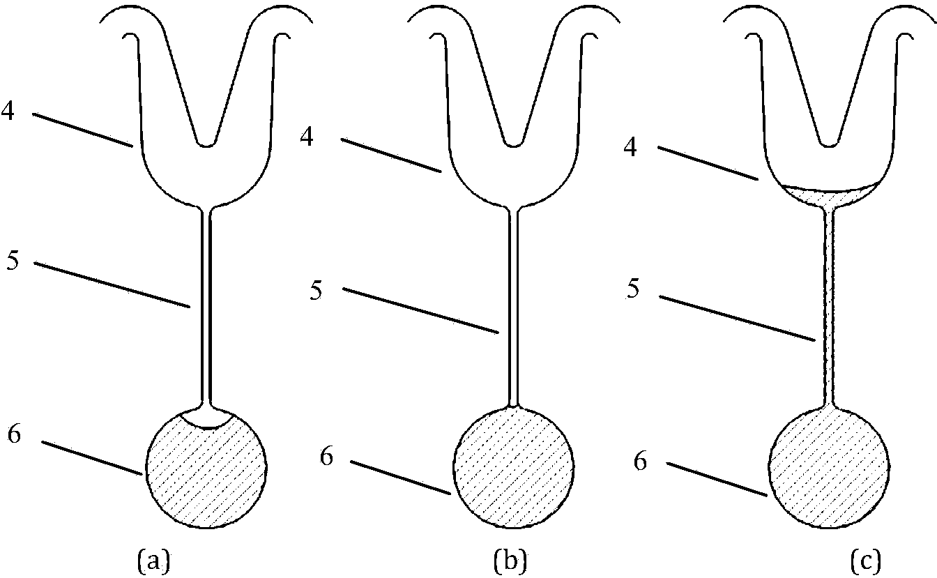
[0047] figure 1 The top view of the microfluidic chip (96-well) for multi-index detection provided by the present invention, figure 2 It is a cross-sectional view of the microfluidic chip of the present invention. The microfluidic chip-backsheet 1 of the present invention and the cover sheet 2 hermetically matched with the backsheet 1 are both double-sided that has the required adhesive strength, can withstand conventional heating temperatures, and has no significant adverse effect on the reactivity performed. The glue fits firmly. A through hole 3 is provided in the center of the microfluidic chip, and a positioning notch 8 is provided at the inner edge of the through hole 3. The through hole 3 and the positioning notch 8 together play a role of positioning, and then play a role in fixing and Positioning functio...


PUM


Abstract

The invention discloses a micro-fluidic chip for multi-index detection. The micro-fluidic chip comprises a substrate and a cover plate which is matched with the substrate in a sealed mode, wherein a through hole is formed in the center of the micro-fluidic chip; one or more wave-shaped main channels are formed in the substrate; one end of each main channel is communicated with a sample introduction hole formed in the substrate, and the other end of each main channel is communicated with an air outlet in the substrate; wave troughs of the main channels are arranged away from the direction of the through hole; wave crests of the main channels are arranged close to the direction of the through hole; any one wave trough of the main channel is communicated with a reaction pool through a connecting pipeline; a buffer pool is arranged on the connecting pipeline. The micro-fluidic chip can be detected by instruments through fluorescence, turbidity and development or is directly observed by naked eyes, can be detected in the reaction process in real time and also can be detected after the reaction is ended.

Description

technical field [0001] The invention relates to a microfluidic chip for multi-index detection, which belongs to the field of microfluidic chips and the field of biological detection. Background technique [0002] Microfluidic chips are currently a hot field in the development of Micro Total Analysis Systems (μ-TAS). It uses chips as an operating platform, and through the combination of technologies such as biology, chemistry, and drug screening, it completes the The whole process including loading, separation, reaction, detection, etc. In recent years, with the rapid development of biochip technology, microfluidic chips are playing an increasingly important role in the fields of life sciences, analytical chemistry and biomedicine. [0003] In order to detect samples efficiently, quickly, and with high throughput, the chip is required to have multiple sets of reaction wells and an effective delivery method for delivering samples to each reaction well. Generally, the microfl...

Claims


Application Information

Patent Timeline
Patent Type & Authority Applications(China)
IPC IPC(8): B01L3/00
CPCB01L3/5027B01L2200/0605B01L2300/0803B01L2300/0864B01L2300/087B01L2400/0409B01L2200/025B01L2300/0851B01L2300/0893C12Q1/6869
Inventor 王磊张国豪周鑫颖辛娟张瑶林明仙黄国亮王璨邢婉丽程京
Owner BOAO BIOLOGICAL CO LTD
Learn More