Method for forming magnetic sensor

A magnetic sensor and magnetic material technology, applied in the field of semiconductors, can solve the problem of low relative change rate of anisotropic magnetoresistance, and achieve the effect of increasing the relative change rate

Active Publication Date: 2014-05-28
SHANGHAI HUAHONG GRACE SEMICON MFG CORP
View PDF5 Cites 9 Cited by
  • Summary
  • Abstract
  • Description
  • Claims
  • Application Information

AI Technical Summary

Problems solved by technology

[0005] The relative rate of change of the anisotropic magnetoresistance formed by the method of the prior art is low

Method used


Image

  • Method for forming magnetic sensor
  • Method for forming magnetic sensor
  • Method for forming magnetic sensor

Examples


Embodiment Construction

[0028] After research and discovery, the reasons for the low relative rate of change of the anisotropic magnetoresistance of the magnetic inductor formed by the method of the prior art are as follows:

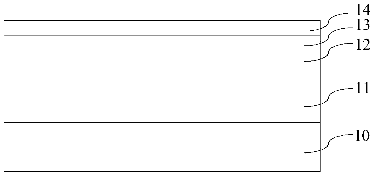
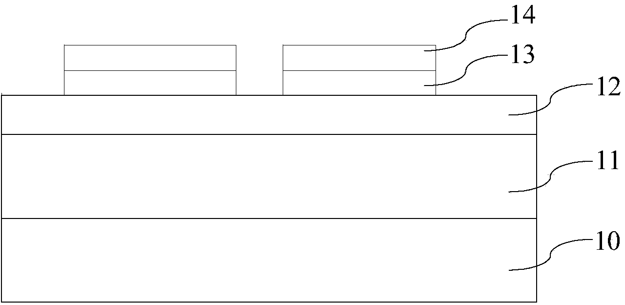
[0029] If a voltage is applied to the subsequently formed magnetic inductor, ideally, the induced current should pass entirely through the nickel-iron layer. In this way, the tantalum nitride layer in contact with the nickel-iron layer will not partly induce current, and the induction signal passing through the nickel-iron layer will not be shunted. Therefore, the subsequently formed magnetic sensor will have a relatively high anisotropic magnetoresistance rate of change. However, in the prior art, referring to figure 2 , if a voltage is applied to the magnetic inductor formed subsequently, part of the induced current will flow through the tantalum nitride layer 14 in contact with the nickel-iron layer 13, so that the induced signal by the nickel-iron layer 13 will be absorbe...


PUM

PropertyMeasurementUnit
thicknessaaaaaaaaaa
thicknessaaaaaaaaaa
thicknessaaaaaaaaaa

Abstract

The invention relates to a method for forming a magnetic sensor. The method comprises the following steps of providing a substrate and forming a magnetic material layer on the substrate; forming a high resistance barrier layer on the magnetic material layer; forming a patterned magnetic material layer and a patterned high resistance barrier layer. The magnetic sensor formed by adopting the method disclosed by the invention is high in relative change rate of anisotropic magnetoresistance.

Description

technical field [0001] The invention relates to the field of semiconductors, in particular to a method for forming a magnetic inductor. Background technique [0002] Magnetic sensors can be used to sense the components of external magnetic fields (such as geomagnetism), and have been widely used in automotive, automation, medical and electronic compass fields. For example, almost every smartphone has an electronic compass. When the magnetic sensor senses the earth's magnetism, it needs a high relative change rate of anisotropic magnetoresistance (dR / R), because the earth's magnetism is very weak, and its size is only 20-60μT. [0003] refer to figure 1 and figure 2 , in the prior art, the forming method of the magnetic inductor is as follows: [0004] refer to figure 1 A substrate 10 is provided, and a silicon oxide layer 11 , a silicon nitride layer 12 , a nickel-iron layer 13 and a tantalum nitride layer 14 are sequentially formed on the substrate 10 from bottom to to...

Claims


Application Information

Patent Timeline
Patent Type & Authority Applications(China)
IPC IPC(8): H01L43/12
Inventor 赵波
Owner SHANGHAI HUAHONG GRACE SEMICON MFG CORP
Why Eureka
Try Eureka