
A thermal error prediction method for heavy machine tools considering ambient temperature

A technology of environmental temperature and prediction method, applied in computer control, program control, instrument, etc., can solve the problems of compensation accuracy failure, limited versatility, non-existence, etc., and achieve the goal of solving poor robustness and improving accuracy and robustness Effect

Active Publication Date: 2017-01-18
WUHAN HENGLI HUAZHEN TECH CO LTD
View PDF3 Cites 0 Cited by
  • Summary
  • Abstract
  • Description
  • Claims
  • Application Information

AI Technical Summary

Problems solved by technology

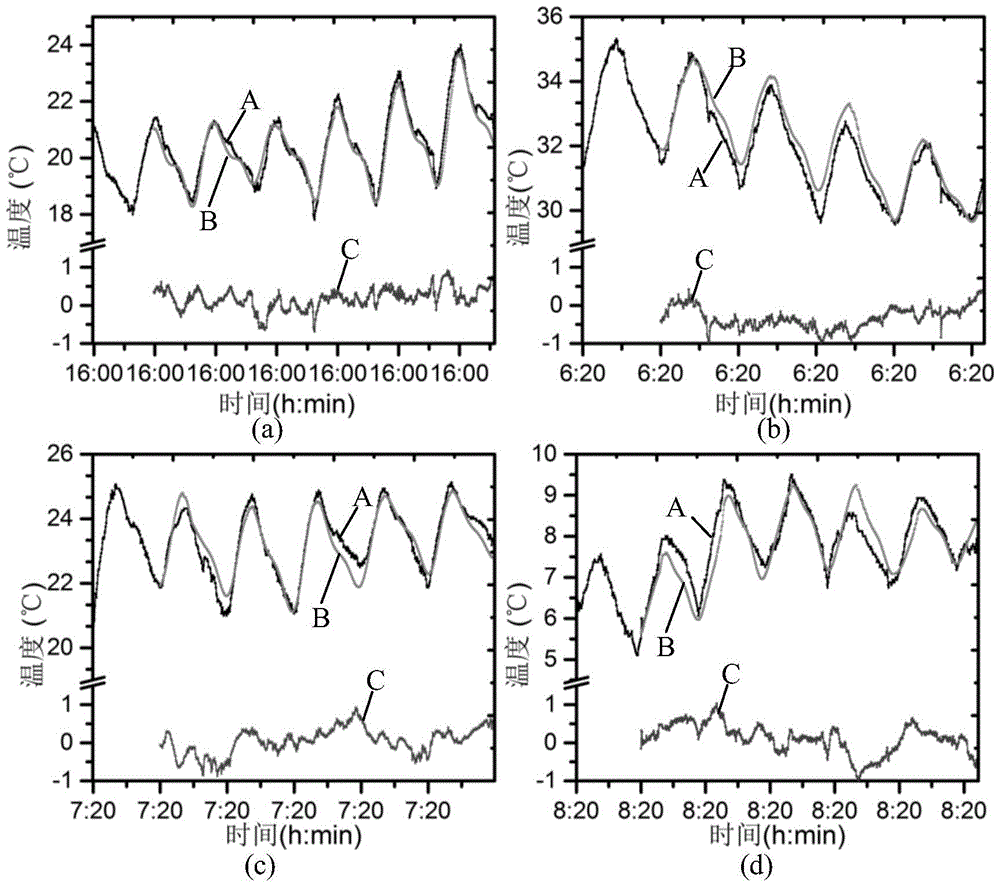
[0005] However, the environmental temperature is different from the optimal distribution characteristics of the machine tool body. The response of heavy-duty machine tools to environmental temperature fluctuations has always lagged behind. There is no recent linear ambient temperature distribution, and the lag time changes with climate and seasonal changes.
However, the current linear and nonlinear thermal error prediction models cannot reflect the hysteresis characteristics with temperature, resulting in limited versatility of the current thermal error prediction model in different environments, and even failure of compensation accuracy.
On the other hand, the current research and analysis on the influence of ambient temperature is limited to experimental measurement, phenomenon description and qualitative discussion, and fails to use its time-lag thermal influence in thermal error modeling and compensation

Method used


Image

  • A thermal error prediction method for heavy machine tools considering ambient temperature
  • A thermal error prediction method for heavy machine tools considering ambient temperature
  • A thermal error prediction method for heavy machine tools considering ambient temperature

Examples


Embodiment Construction

[0039]In order to make the object, technical solution and advantages of the present invention clearer, the present invention will be further described in detail below in conjunction with the accompanying drawings and embodiments. It should be understood that the specific embodiments described here are only used to explain the present invention, not to limit the present invention. In addition, the technical features involved in the various embodiments of the present invention described below can be combined with each other as long as they do not constitute a conflict with each other.

[0040] One, the technical thought of the present invention.

[0041] The thermal deformation error of the machine tool is decomposed into the superposition of the influence of the external environment and the internal heat source. X represents the specified thermal deformation direction to be measured, which can be the x coordinate, y coordinate and z coordinate direction in the machine tool coor...


PUM


Abstract

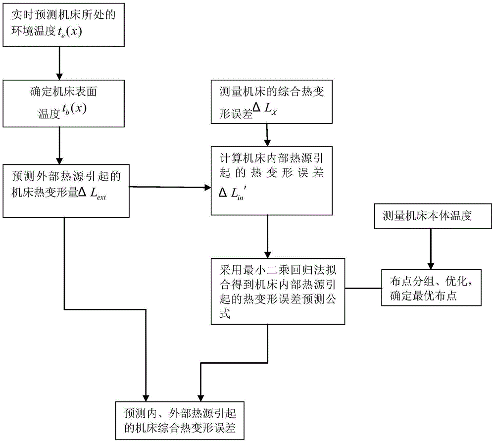
The invention discloses a heavy-duty tool thermal deformation prediction method taking environmental temperature into account. The method specifically comprises the following steps of predicting the tool thermal deformation caused by the internal heat source of a tool, predicting tool thermal deformation caused by the external heat source of the tool, summing the tool thermal deformation caused by the internal and external heat sources to obtain the final tool thermal deformation. Time-lag thermal deformation error caused by the environmental temperature is taken into account during the prediction of the tool thermal deformation caused by the external heat source of the tool, and multiple regression modelling based on the least square method principle is performed during the prediction of the tool thermal deformation caused by the internal heat source of the tool. The joint action effects reflecting the influence of the environment temperature nonlinear lag and the influence of the internal heat source on the heavy-duty tool are combined by the method, and the thermal deformation error under any environmental condition and processing condition can be effectively predicted in real time.

Description

technical field [0001] The invention relates to the technical field of thermal error compensation of numerical control machine tools, and more specifically relates to a method for predicting thermal errors of heavy-duty machine tools in consideration of ambient temperature. Background technique [0002] Under non-constant temperature conditions, the combined effect of internal heat source and external environment on CNC machine tools produces nonlinear temperature response and thermal deformation of complex structures, resulting in reduced machining accuracy or even failure of accuracy. Prediction and compensation of thermal errors are important means to improve the machining accuracy of CNC machine tools and the thermal stability of machine tools. With the analysis of the influence mechanism of internal heat sources and the reduction methods of thermal errors becoming more and more mature, the thermal errors caused by the ambient temperature on the machine tools account for ...

Claims


Application Information

Patent Timeline
Patent Type & Authority Patents(China)
IPC IPC(8): G06F19/00G05B19/404
Inventor 李斌谭波毛新勇毛宽民任光远彭芳瑜刘红奇
Owner WUHAN HENGLI HUAZHEN TECH CO LTD
Learn More