
Method and device for testing thermal performance of LED radiator

A technology of LED radiator and testing device, applied in the direction of thermal conductivity of materials, etc., can solve the problems of complex fixing device, inability to realize the thermal performance test of radiator, affecting the natural convection of radiator, etc., achieving wide application range, simple structure, clamping Tightening effect

Active Publication Date: 2014-05-28
NANJING UNIV OF AERONAUTICS & ASTRONAUTICS
View PDF8 Cites 13 Cited by
  • Summary
  • Abstract
  • Description
  • Claims
  • Application Information

AI Technical Summary

Problems solved by technology

At present, the common LED heat sink thermal performance test device has complicated fixing devices, which affects the natural convection around the heat sink, and cannot realize the thermal performance test under the inclined placement of the heat sink

Method used


Image

  • Method and device for testing thermal performance of LED radiator
  • Method and device for testing thermal performance of LED radiator
  • Method and device for testing thermal performance of LED radiator

Examples


Embodiment 1

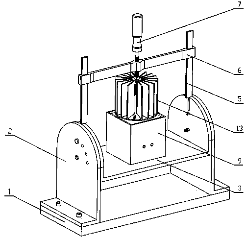
[0037] Such as figure 1 , 3 shown.

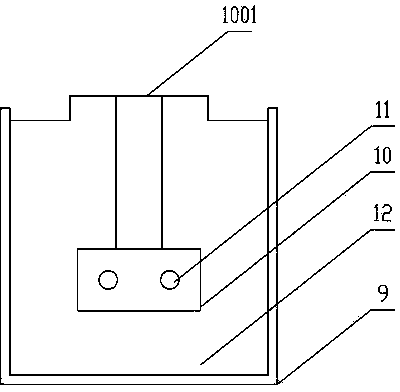
[0038] A method for testing the thermal performance of an LED heat sink. The end surface of a heating block 10 made of pure copper is used as a heating surface 1001 to simulate the heat source of an LED chip. The heating block 10 is embedded with an electric heating tube 11, which is placed in the containing box 9 and is surrounded by a heat insulating material 12, so that the heat generated by the electric heating tube 11 can be almost completely transferred to the end surface of the copper block, and the power supply connected to the electric heating tube 11 can be adjusted. The magnitude of the current can change the magnitude of the heat flux reaching the heating surface 1001, thereby simulating LED chips with different powers.

[0039] The radiator 13 to be tested is placed between the heating surface 1001 and the screw 7, the heating surface of the radiator is aligned with the heating surface 1001 of the copper block, and the centra...

Embodiment 2

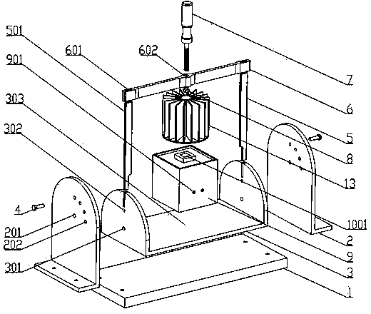
[0042] Such as Figure 1-5 shown.

[0043] A heat performance testing device for an LED radiator includes a rotating device, a fixing device and a heat source simulation device.

[0044] The rotating device includes a base 1, a supporting frame 2 and a U-shaped rotating frame 3. The two supporting frames 2 are fixed on both ends of the base 1 with screws. The opposite second hinged hole 301 can be hinged by bolts and nuts. On the support frame, with the first hinge hole 201 as the center, a plurality of first positioning holes 202 are evenly distributed within 90°, the number of which can be set according to the required test angle, and the positions of the positioning holes on the support frames 2 on both sides are arranged symmetrically. The two ends of the swivel frame 3 also have a corresponding second positioning hole 302, one of the first and second positioning holes is opposite, and the stop pin 4 is inserted, so that the swivel frame can be rotated and fixed at a ce...


PUM


Abstract

The invention discloses a method and a device for testing thermal performance of an LED radiator. The method is characterized in that a heating block end surface made of a pure copper material is taken as a heating surface to simulate an LED chip heat source; electric heating tubes are embedded in the heating block which is wrapped with a thermal insulating material, and heat generated by the electric heating tubes is almost completely transmitted to the copper block end surface; the tested radiator is placed between the heating surface and a screw rod, a heated surface of the radiator aligns to the copper block heating surface, and the screw rod is tightened to enable the radiator and the heating surface to be tightly contacted; and the simulated heat source and guide rods are all fixed on a rotatable rack and relatively rotate with a hinged hole as a center by means of respective positioning holes in the rotatable rack and support racks, so that the heat dissipation performance when the radiator is placed obliquely can be tested. The invention further provides the testing device used for the testing method. According to the method and the device for testing the thermal performance of the LED radiator, the application range is wide, the structure is simple, and parts are convenient to process and assemble.

Description

technical field [0001] The present invention relates to a LED detection technology, especially a method and device for testing the thermal performance of LED radiators, in particular to a method and device for testing the thermal performance of LED radiators, which can simulate heat sources in the testing of LED radiators , and can test the heat dissipation performance when the radiator is placed at an angle. Background technique [0002] Generally, only 20%~30% of the electrical energy of LED chips is converted into light energy, and the remaining 70%~80% is mainly converted into heat energy in the form of point vibrations that occur through non-radiative recombination. If the heat cannot be dissipated in time, the junction temperature of the LED will rise rapidly, which will affect the life cycle, luminous efficiency and stability of the product. Therefore, a heat sink with efficient thermal performance is particularly important for LED devices. [0003] Judging the ther...

Claims


Application Information

Patent Timeline
Patent Type & Authority Applications(China)
IPC IPC(8): G01N25/18
Inventor 周驰左敦稳孙玉利左宇杰
Owner NANJING UNIV OF AERONAUTICS & ASTRONAUTICS
Learn More