
Array substrate and preparation method and display panel

A technology of array substrates and substrate substrates, which is applied in semiconductor/solid-state device manufacturing, instruments, semiconductor devices, etc., can solve the problems of panel image quality degradation, enhanced leakage paths, unfavorable charges, etc., to reduce off-state leakage current, Increase the off-state resistance to improve the flickering effect of the screen

Inactive Publication Date: 2014-05-21
HEFEI XINSHENG OPTOELECTRONICS TECH CO LTD +1
View PDF5 Cites 12 Cited by
  • Summary
  • Abstract
  • Description
  • Claims
  • Application Information

AI Technical Summary

Problems solved by technology

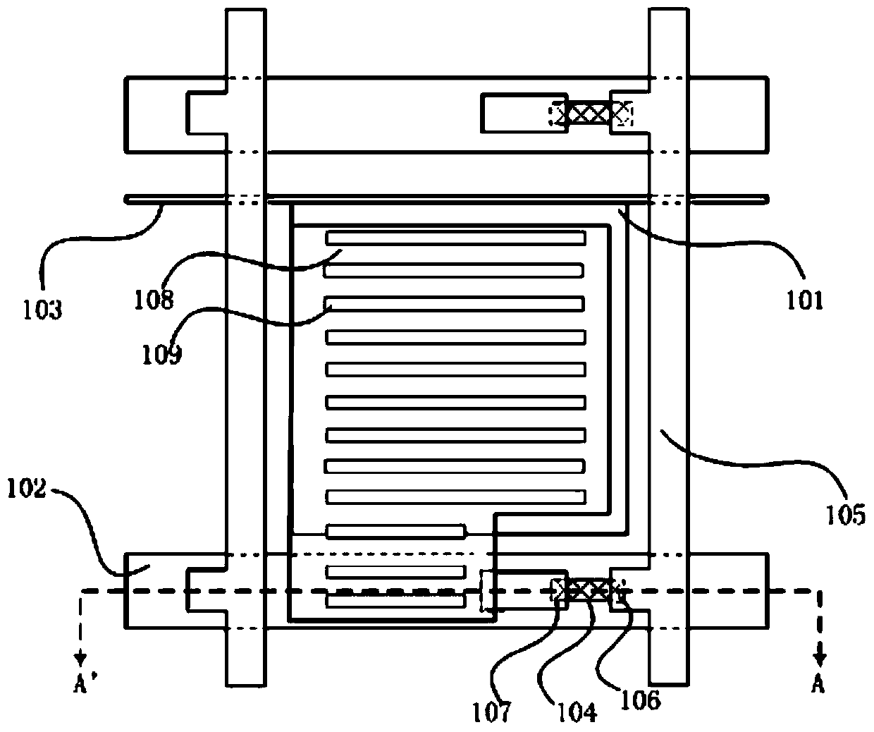
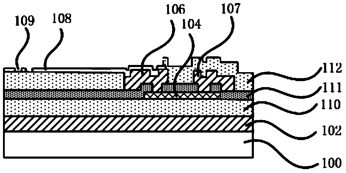
However, in the oxide TFT with this light-shielding structure, the source electrode 106 and the drain electrode 107 are directly in contact with the oxide active layer 104, which will cause holes in the oxide active layer 104 to flow into the source electrode 106 and the drain electrode 107, And the probability of electrons flowing into the active layer 104 from the source 106 and the drain 107 increases, thereby strengthening the leakage path of "drain → oxide TFT active layer → source", which is not conducive to maintaining the stored charge. Deterioration of panel quality

Method used


Image

  • Array substrate and preparation method and display panel
  • Array substrate and preparation method and display panel
  • Array substrate and preparation method and display panel

Examples


Embodiment Construction

[0062] The specific implementation manners of the present invention will be further described in detail below in conjunction with the accompanying drawings and embodiments. The following examples are used to illustrate the present invention, but should not be used to limit the scope of the present invention.

[0063] It should be noted that "upper" and "lower" in the embodiments of the present invention are only used to describe the embodiments of the present invention with reference to the drawings, and are not used as limiting terms. In the description of the embodiments of the present invention, the terms "first" and "second" are used for description purposes only, and cannot be understood as indicating or implying relative importance or implicitly indicating the quantity of indicated technical features.

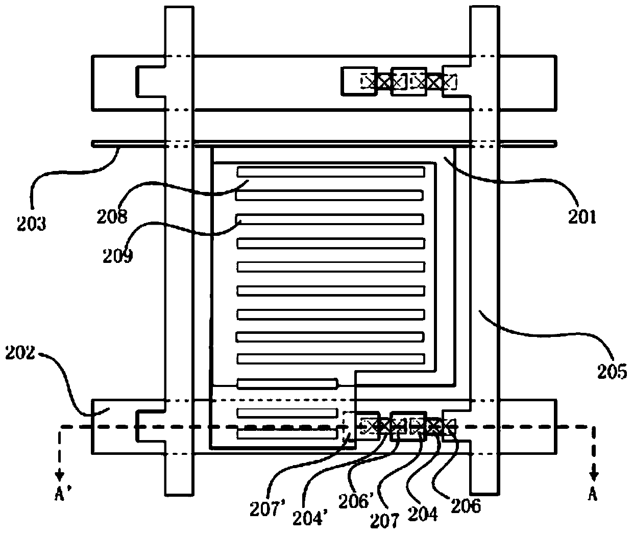
[0064] In this embodiment, the structure of the TFT array substrate is specifically described by taking the structure of an advanced dimension switch (Advanced Dimension ...


PUM


Abstract

The invention discloses an array substrate and a preparation method thereof and a display panel. The array substrate can reduce the leakage current of a thin film transistor and is used for improving the phenomena of flicker, crosstalk, residual images and the like of the display panel and improving display performance. The array substrate comprises a substratum substrate and grid lines, data lines and a plurality of pixel units which are arranged on the substratum substrate, wherein each pixel unit comprises a first oxide thin film transistor and pixel electrodes. The array substrate is characterized in that each pixel unit also comprises at least one second oxide thin film transistor which is connected in series with the first oxide thin film transistor; the pixel electrodes are connected with a drain electrode of the second oxide thin film transistor; a source electrode of the second oxide thin film transistor is connected with a drain electrode of the first oxide thin film transistor; a source electrode of the first oxide thin film transistor is connected with the data lines; and the second oxide thin film transistor is connected in series with the first oxide thin film transistor to increase off resistance between the pixel electrodes and the data lines. The embodiment of the invention is applied to the technical field of display.

Description

technical field [0001] The present invention generally relates to the technical field of liquid crystal display, and specifically relates to an array substrate, a manufacturing method thereof, and a display panel. Background technique [0002] Thin Film Transistor (TFT) leakage paths mainly include liquid crystal capacitor leakage and TFT leakage. The former leaks from the pixel electrode to the common electrode, and the latter leaks from the pixel electrode to the data line. Therefore, the leakage of the latter will be connected to the data line. related to the voltage. The leakage current conduction mechanism of the TFT device itself is mainly the hole current formed by channel thermionic emission, and the leakage current of traditional amorphous silicon products will increase dramatically under the condition of light. [0003] Indium Gallium Zinc Oxide (IGZO) is a new generation of material for the active layer of TFT. IGZO solves the defects of traditional TFT: the crys...

Claims


Application Information

Patent Timeline
IPC IPC(8): H01L27/12H01L21/77G02F1/1362G02F1/1368
CPCG02F1/13624H01L27/1222H01L27/1225H01L27/1288H01L21/77H01L29/786H01L27/12H01L27/124H01L27/1248H01L29/04H01L29/16H01L29/22H01L29/24H01L29/66765H01L29/66969H01L29/78678H01L29/7869
Inventor 蒋学兵林琳
Owner HEFEI XINSHENG OPTOELECTRONICS TECH CO LTD
Learn More