
A highly fuel-efficient engine

A technology of engine and transmission mechanism, applied in the direction of machines/engines, mechanical equipment, etc., can solve the problems of reducing gas volume compression ratio, only proper delay, low fuel utilization efficiency, etc.

Inactive Publication Date: 2018-01-02
孙露婷
View PDF11 Cites 0 Cited by
  • Summary
  • Abstract
  • Description
  • Claims
  • Application Information

AI Technical Summary

Problems solved by technology

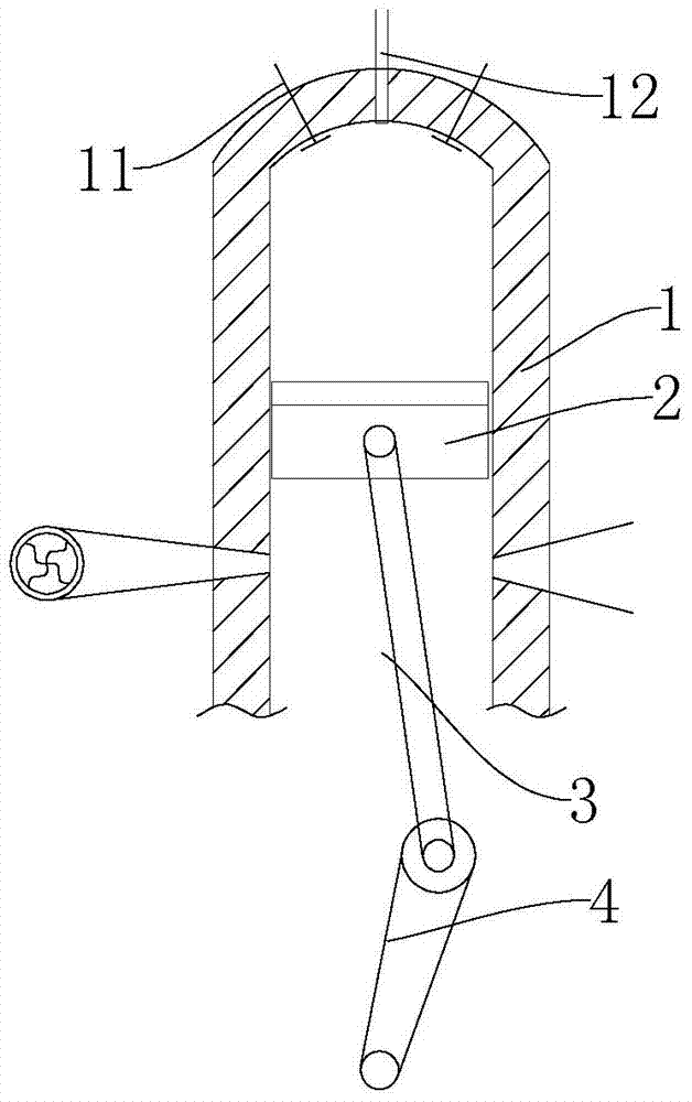
Among them, when the piston moves to the top dead center of the cylinder, the gas is compressed to the smallest volume, that is, the compression ratio is the highest. At this moment, the explosion thrust generated by the gas ignited will be the largest, but at this time the connecting rod and the crankshaft that drive the piston are in a straight line In general, the length of the moment arm between the connecting rod and the crankshaft is very small, or even zero, so the torque obtained on the crankshaft is very small, so the ignition can only be delayed properly. When there is a certain moment arm length between the crankshafts, re-ignite to increase the torque to push the crankshaft, which will inevitably reduce the compression ratio of the gas volume and make the fuel efficiency low

Method used


Image

  • A highly fuel-efficient engine
  • A highly fuel-efficient engine
  • A highly fuel-efficient engine

Examples


Embodiment Construction

[0021] Such as figure 1 Shown is a prior art engine, including a cylinder 1, a main piston 2 reciprocating in the cylinder 1, a connecting rod 3 connected to the main piston 2, a crankshaft 4 driven by the connecting rod 3, and a spark plug 11 at the top of the cylinder 1 and the fuel injector 12, when the main piston 2 moves to the top in the cylinder 1, the fuel injector 12 injects fuel, the spark plug 11 ignites and explodes, and then pushes the piston 2 to move downward in the cylinder 1, and then drives the crankshaft 4 to move, when the piston 2 At the top dead center, the compression ratio of piston 2 in cylinder 1 is the highest (compression ratio is the ratio of the total volume of the cylinder to the volume of the combustion chamber), at this time, the ignition of the spark plug 11 can release the maximum explosive energy to become the power output of the engine , but while maintaining a high compression ratio, the length of the moment arm between the connecting rod ...


PUM


Abstract

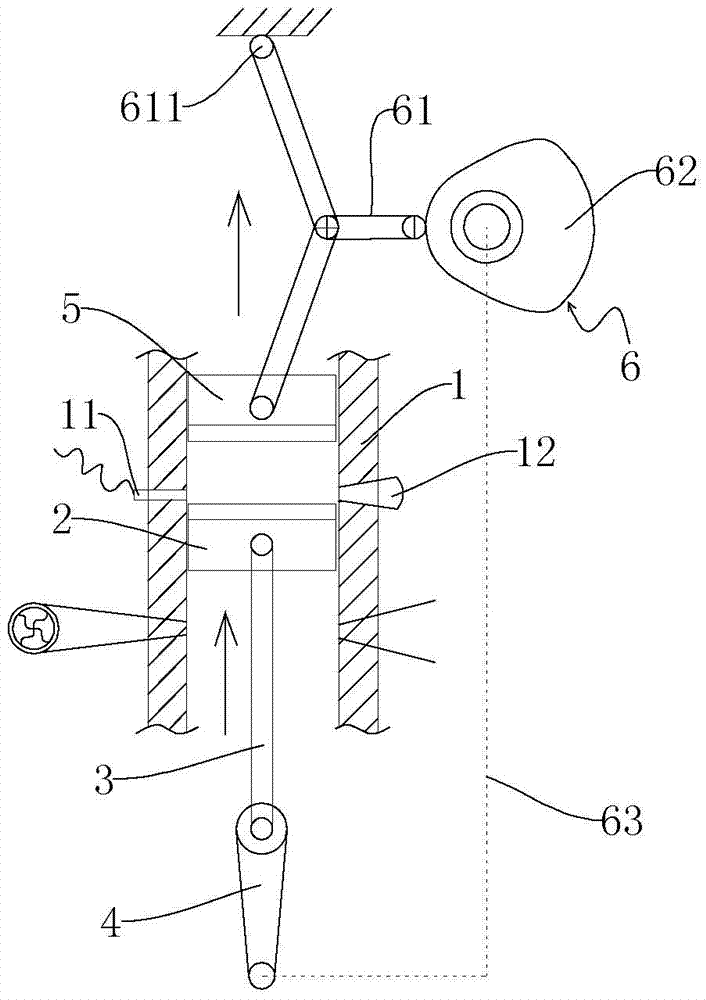
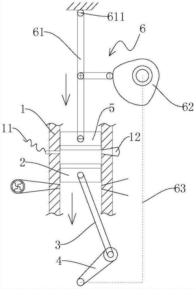
The invention discloses a highly oil-saving engine. According to the highly oil-saving engine, gas is ignited and explodes when the force arm length between a connecting rod and a crankshaft is large, then a high force moment generates on the crankshaft and simultaneously a high gas compression ratio is maintained. The highly oil-saving engine comprises an air cylinder, a main piston, the connecting rod, the crankshaft, sparking plugs and an oil nozzle, wherein the main piston does reciprocating movements in the air cylinder, the connecting rod is connected with the main piston, the crankshaft is driven by the connecting rod to rotate, and the sparking plugs and the oil nozzle are located in the air cylinder. An auxiliary piston which is used in cooperation with the main piston to do up-down reciprocating movements as the main piston is arranged above the main piston in the air cylinder. The sparking plugs and the oil nozzle are located between the main piston and the lower dead center of the auxiliary piston. Compared with the prior art, the highly oil-saving engine has the advantages that the highly oil-saving engine is of the double-piston structure that the auxiliary piston is additionally arranged above the main piston so that the high gas compression ratio can be maintained when the main piston in the air cylinder moves downwards; the gas is ignited and explodes when the force arm length between the connecting rod and the crankshaft is large, then the high force moment can generate on the condition of low oil consumption, and consequently the purpose of saving oil is achieved.

Description

technical field [0001] The invention relates to a fuel-burning engine, in particular to a highly fuel-saving engine that efficiently utilizes fuel explosion thrust in the engine cylinder, can adjust the compression ratio, and can use various fuels. Background technique [0002] There is only one movable piston in the current fuel engine cylinder, which reciprocates in the cylinder and turns into a rotating power output through the connecting rod and crankshaft mechanism. It consists of four working strokes: air intake, compression, ignition and explosion, and exhaust. Among them, when the piston moves to the top dead center of the cylinder, the gas is compressed to the smallest volume, that is, the compression ratio is the highest. At this moment, the explosion thrust generated by the gas ignited will be the largest, but at this time the connecting rod and the crankshaft that drive the piston are in a straight line In general, the length of the moment arm between the connect...

Claims


Application Information

Patent Timeline
Patent Type & Authority Patents(China)
IPC IPC(8): F02B75/28
Inventor 孙露婷佟昊蔣宗銓
Owner 孙露婷
Learn More