
Two-way drive roving frame

A two-way transmission and roving frame technology, which is applied to spinning machines, continuous winding spinning machines, textiles and papermaking, etc., can solve the problems of rising equipment manufacturing and maintenance costs, increasing equipment failure risk index, small lifting drive shaft Torque and other problems, to achieve the effect of improving the output and production efficiency of a single machine, the increase of equipment manufacturing cost is small, and the number of spindles is increased

Active Publication Date: 2016-02-03
CMT HICORP MACHINERY QINGDAO
View PDF6 Cites 0 Cited by
  • Summary
  • Abstract
  • Description
  • Claims
  • Application Information

AI Technical Summary

Problems solved by technology

[0005] The above technical solution only solves the technical problem of how to share the torque on the lifting transmission shaft during the lifting of the dragon tendon in order to keep the lower torque on the lifting transmission shaft when the number of spindles on the dragon tendon increases.
Moreover, the increase in the number of spindles of the roving frame adopting the above-mentioned technical scheme is still limited, and due to the relatively complicated motion trajectory during its working process, on the one hand, it brings about a complicated control system and increased control difficulty; on the other hand, its equipment structure is complicated, and equipment failures The risk index increases, which brings about the increase of equipment manufacturing and maintenance and repair costs

Method used


Image

  • Two-way drive roving frame
  • Two-way drive roving frame
  • Two-way drive roving frame

Examples


Embodiment Construction

[0028] The two-way transmission roving frame of the present invention will be described in detail below in conjunction with the accompanying drawings.

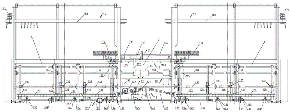
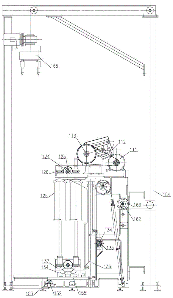
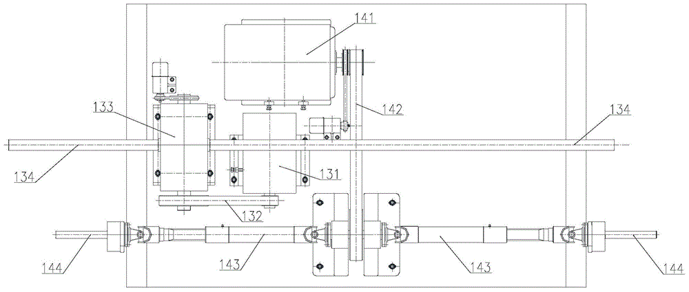
[0029] Such as figure 1 As shown, the two-way transmission roving frame mechanism of the present invention includes a headstock 1, a vehicle body 2, and a power output part. The power output part is arranged inside the headstock 1, and the power output of the roving frame is transmitted from the headstock 1 to the body 2 located on the left and right sides thereof.

[0030] The power input part of the above-mentioned roving frame adopts a power source and a set of power control system; the above-mentioned left section body and right section body are preferably symmetrically distributed on the left and right sides of the headstock 1 .

[0031] For ease of understanding, the attached Figure 1-3 , taking the automatic doffing roving frame as an example, the four major motion components required for the spinning process of the ...


PUM


Abstract

The invention discloses a bidirectional transmission roving frame which comprises a frame head, a frame body and a power output part an is characterized in that the frame body is divided into a left section and a right section which are arranged on two sides of the frame head, the power output part is arranged in the frame head, and the power output mode of the roving frame is that the power is transmitted to the left section and the right section of the frame body from the frame head. A power input part of the roving frame adopts a power source and a power control system. Preferably, the left-section frame body and the right-section frame body are distributed on the left side and the right side of the frame head symmetrically. According to the bidirectional transmission roving frame, a slight structural improvement is performed on the existing roving frame, the number of spindles of the roving frame is greatly increased, and one-machine yield and production efficiency of the roving frame are increased greatly. Furthermore, manufacture cost increase of the device is small, maintenance and device management are convenient, the fault rate of the device is low, and spinning quality is good.

Description

technical field [0001] The invention relates to a roving frame, in particular to a two-way transmission roving frame, which belongs to the field of textile machinery. Background technique [0002] In the prior art, the power transmission of the roving frame is unilaterally driven from the headstock, so-called left and right hand carts. The roving frame of this structure in the prior art directly restricts the increase of its stand-alone output, mainly because: if the number of spindles needs to be increased, the body must be lengthened, and the lengthening of the body will cause a large torque on the transmission part of the entire equipment , resulting in poor synchronization of the operation of each spindle position, and the control is very difficult. Moreover, the increase in the number of spindles of this roving frame is limited by the increase in the length of the body, for example, the longest roving frame with a spindle gauge of 220mm can only reach 156 spindles; the...

Claims


Application Information

Patent Timeline
Patent Type & Authority Patents(China)
IPC IPC(8): D01H1/32
Inventor 崔桂华李建霞刘伟王成吉任义利周春娟徐先晓郭加阳
Owner CMT HICORP MACHINERY QINGDAO
Learn More