Automatic gate milling machine

A gating and automatic technology, which is applied in the direction of milling machine equipment, milling machine equipment details, metal processing machinery parts, etc., can solve the problems of hidden safety hazards, low milling precision, and low processing efficiency, so as to reduce labor intensity and work stability Good performance and high processing efficiency

Active Publication Date: 2016-05-04
泰成半导体精密(苏州)有限公司
View PDF8 Cites 0 Cited by
  • Summary
  • Abstract
  • Description
  • Claims
  • Application Information

AI Technical Summary

Problems solved by technology

[0002] Cup-shaped injection molded parts need to mill the gate. The existing method is to use a vertical milling machine, place the workpiece on the workbench and press it with your hand to perform manual milling. The disadvantages of the existing technology are: 1) There is no special positioning and clamping mechanism , clamping is unreliable; 2) manual operation, there are potential safety hazards; 3) one-handed positioning, one-handed operation, resulting in low milling accuracy; 4) low processing efficiency during mass production; 5) since the gate is located in the cavity at the bottom of the shell Inside, while the vertical milling machine spindle is above the workpiece, chip removal is inconvenient

Method used


Image

  • Automatic gate milling machine
  • Automatic gate milling machine
  • Automatic gate milling machine

Examples


Embodiment Construction

[0023] The present invention will be described in detail below with reference to the accompanying drawings and in combination with embodiments.

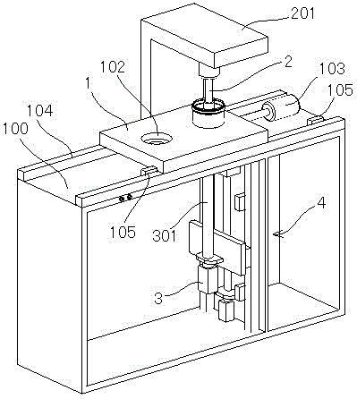
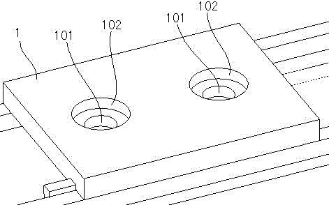
[0024] refer to figure 1 , image 3 As shown, an automatic gate milling machine includes a compression cylinder 2 disposed above the workpiece positioning plate 1, a spindle motor 3 disposed below the workpiece positioning plate 1, and a feed mechanism 4 that drives the spindle motor 3 to feed. The workpiece positioning plate 1 is provided with an escape hole 101, and the spindle motor 3 is connected with a main shaft 301 and a milling cutter in sequence. The axis of the avoidance hole 101 coincides with the axis of the main shaft 301. The axis of the cylinder 2 is parallel to the feeding direction of the feeding mechanism 4 . The main shaft 301 is arranged under the workpiece, which is beneficial to chip removal and avoids the process of manual cleaning.

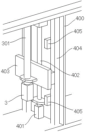
[0025] refer to figure 2 As shown, the feed mechanism 4 includes a screw...


PUM


Abstract

The invention discloses an automatic gate milling machine, comprising a compressing cylinder, a spindle motor and a feeding mechanism, wherein the compressing cylinder is arranged above a work-piece locating plate; the spindle motor is arranged below the work-piece locating plate; the feeding mechanism drives the spindle motor to feed; an avoiding hole is formed in the work-piece locating plate; a spindle and a milling cutter are orderly connected to the spindle motor; the avoiding hole overlaps with the axis of the spindle; the axis of the spindle, the axis of the compressing cylinder and the feeding mechanism are parallel in direction. The work-piece locating plate is arranged on the automatic gate milling machine, a locating groove is formed inside the locating plate, and the device is clamped by adopting the compressing cylinder, so that the automatic gate milling machine is reliable to clamp and high in automatic processing efficiency, and the labor intensity of a worker is reduced.

Description

technical field [0001] The invention relates to an automatic gate milling machine. Background technique [0002] Cup-shaped injection molded parts need to mill the gate. The existing method is to use a vertical milling machine, place the workpiece on the workbench and press it with your hand to perform manual milling. The disadvantages of the existing technology are: 1) There is no special positioning and clamping mechanism , clamping is unreliable; 2) manual operation, there are potential safety hazards; 3) one-handed positioning, one-handed operation, resulting in low milling accuracy; 4) low processing efficiency during mass production; 5) since the gate is located in the cavity at the bottom of the shell Inside, while the spindle of the vertical milling machine is above the workpiece, chip removal is inconvenient. Contents of the invention [0003] The object of the present invention is to overcome the above problems existing in the prior art, and provide an automatic...

Claims


Application Information

Patent Timeline
Patent Type & Authority Patents(China)
IPC IPC(8): B23C3/00B23Q3/08B23Q5/32
Inventor 屠春娟石皋莲顾涛
Owner 泰成半导体精密(苏州)有限公司
Why Eureka
Try Eureka