DC plug metal contact and metal contact flat cable capable of automatically crimping

A metal contact and plug technology, applied in contact parts, contact manufacturing, riveting connection, etc., can solve the problems of affecting the performance of DC plugs, uneven solder joint size, low production efficiency, etc., to avoid poor welding, improve Production efficiency, the effect of saving production costs

Inactive Publication Date: 2014-05-14
东莞市中普电子科技有限公司
View PDF16 Cites 1 Cited by
  • Summary
  • Abstract
  • Description
  • Claims
  • Application Information

AI Technical Summary

Problems solved by technology

[0002] A DC plug is a connector used to connect a power supply to a DC power supply, usually such as a computer plug, a mobile phone charger plug, etc.; at present, a DC plug usually includes a casing 10 formed by injection molding of a metal conduit 7, and the inner elastic contact piece 4 is inserted into the socket. It is formed in the casing. When installing the wires, it is necessary to weld the two wires 11 to the end of the metal conduit 7 and the tail of the inner spring contact piece 4 respectively. When forming a product, it is also necessary to inject plastic at the tail. When welding the wires Generally, manual spot welding is used, and the production efficiency is low ( figure 1 It is a schematic diagram of the structure of the DC plug in the prior art); there will also be quality problems caused by poor welding, and due to human factors, the size of the solder joints is not uniform, resulting in variable resistance of the line connected to the DC plug, which affects the performance of the DC plug

Method used


Image

  • DC plug metal contact and metal contact flat cable capable of automatically crimping
  • DC plug metal contact and metal contact flat cable capable of automatically crimping
  • DC plug metal contact and metal contact flat cable capable of automatically crimping

Examples


Embodiment Construction

[0021] Attached below Figure 2-8 The present invention is described further:

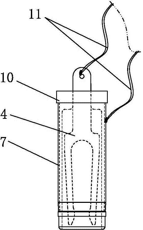
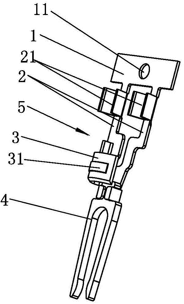
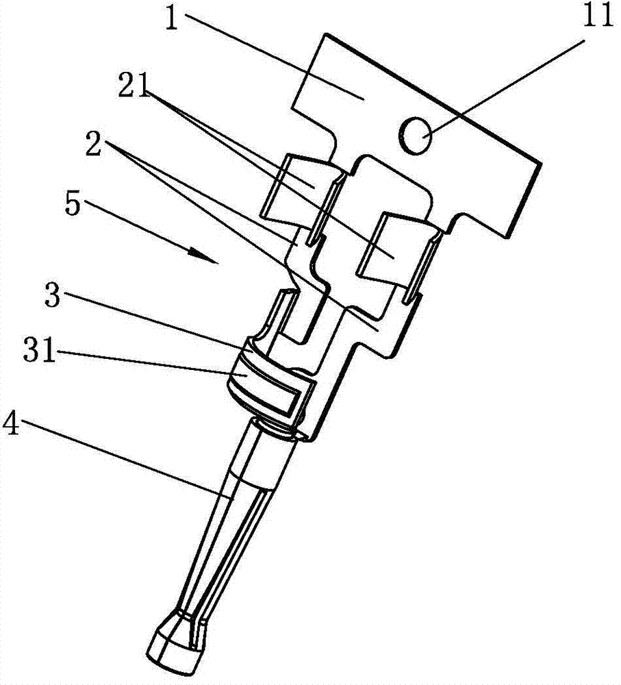
[0022] A DC plug metal contact for automatic termination, the metal contact 5 includes a horizontal connecting piece 1, two connecting pieces 2 are arranged vertically to the same side on the horizontal connecting piece 1, and the end of a connecting piece 2 is set for With the semi-annular contact piece 3 connected to the metal conduit 7, the inner elastic contact piece 4 is arranged at the end of the other connecting piece 2, and the semi-annular contact piece 3 is arranged in the shape of surrounding the inner elastic contact piece 4, and the connecting piece 2 is in the A wire riveting position 21 is set close to the position of the transverse connecting piece 1 .

[0023] In order to save costs and adapt to automatic production, the inner elastic contact piece 4 is riveted on the end of the connecting piece 2. Through two different materials, the inner elastic contact piece 4 is thicker than ...


PUM


Abstract

The invention relates to the technical field of a DC plug, and particularly relates to a DC plug metal contact and a metal contact flat cable capable of automatically crimping. According to the DC plug metal contact, a half-ring-shaped contact plate and an inner elastic contact plate are connected with transverse connect plates through two connect plates, the connect plates are provided with wire riveting positions near the position of the transverseconnect plates, when the DC plug is produced, an interpolation core formed by the metal contact is arranged inside an insulation coat shell in an inserting mode, and the half-ring-shaped contact plate is in contact with a bare contact part of the coat shell. Two wires which are required to be connected are crimped on the riveting positions of the connect plates of the half-ring-shaped contact plate and the inner elastic contact respectively through an automatic crimping machine, and the two wires are cut on the transverseconnect plates, so that the tight connection is assured, quality problem caused by traditionally welding is avoided, and production efficiency is improved. When a DC plug flat cable is formed by a whole chain of transverse connect plates, the transverse connect plates can be formed into a tray and can be arranged on the crimping machine to automatically crimp the wires, and work efficiency is improved.

Description

technical field [0001] The invention relates to the technical field of DC plugs, in particular to a DC plug metal contact and a metal contact cable for automatic termination. Background technique [0002] A DC plug is a connector used to connect a power supply to a DC power supply, usually such as a computer plug, a mobile phone charger plug, etc.; at present, a DC plug usually includes a casing 10 formed by injection molding of a metal conduit 7, and the inner elastic contact piece 4 is inserted into it. It is formed in the casing. When installing the wires, it is necessary to weld the two wires 11 to the end of the metal conduit 7 and the tail of the inner elastic contact piece 4 respectively. When forming a product, it is also necessary to inject plastic at the tail. When welding the wires Generally, it is manual spot welding, and the production efficiency is low ( figure 1 It is a schematic diagram of the structure of the DC plug in the prior art); there will also be qu...

Claims


Application Information

Patent Timeline
Patent Type & Authority Applications(China)
IPC IPC(8): H01R13/02H01R13/24H01R4/06H01R43/16
Inventor 周武
Owner 东莞市中普电子科技有限公司
Why Eureka
Try Eureka