Exposure mechanism of optical touch system and optical touch system using same

An optical touch and mechanism technology, applied in the input/output process of data processing, instruments, electrical digital data processing, etc., can solve the problems of long time spent and reduced image synchronization, so as to shorten the time and shorten the total sampling time, the effect of increasing the operating frequency of the system

Inactive Publication Date: 2014-05-14
PIXART IMAGING INC
View PDF5 Cites 6 Cited by
  • Summary
  • Abstract
  • Description
  • Claims
  • Application Information

AI Technical Summary

Problems solved by technology

Assuming that the sampling time of the image sensors 921-924 is T, all the image sensors 921-924 have acquired a bright image I ON and a dark image I OFF A total of 8T time must be spent, which will reduce the synchronization of the images acquired by the image sensors 921-924
Especially when the number of image sensors is larger, it takes longer for all image sensors to acquire a bright image and a dark image

Method used


Image

  • Exposure mechanism of optical touch system and optical touch system using same
  • Exposure mechanism of optical touch system and optical touch system using same
  • Exposure mechanism of optical touch system and optical touch system using same

Examples


Embodiment Construction

[0037] In order to make the above and other objects, features, and advantages of the present invention more apparent, a detailed description will be given below with reference to the accompanying drawings. In the description of the present invention, the same components are denoted by the same symbols, and they will be described in advance.

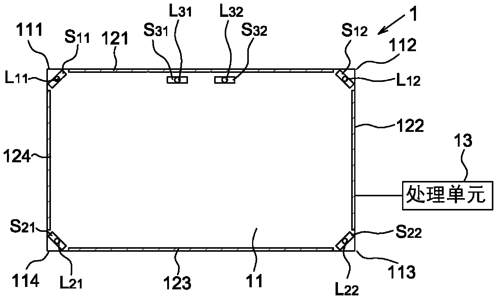
[0038] Please refer to figure 2 As shown, it shows a schematic diagram of an optical touch system according to an embodiment of the present invention. The optical touch system 1 of this embodiment includes a touch surface 11, a plurality of image sensors (such as S 11 , S 12 , S 21 , S22 , S 31 , S 32 ), a plurality of strip light sources 121-124 and a processing unit 13. The image sensor can be a CCD image sensor, a CMOS image sensor or other sensing devices for obtaining image data, which is used to obtain image frames across the touch surface 11; wherein, the image sensor can be set, for example on the corners (such as 111 - 11...


PUM


Abstract

Disclosed is an exposure mechanism of an optical touch system. The optical touch system comprises multiple image sensors and multiple active light sources, and each active light source emits light correspondingly to the related image sensor. The exposure mechanism includes that the image sensors are used for acquiring image frames by sampling circulation to enable each image sensor to acquire a bright image, wherein the sampling circulation includes multiple working modes, and at least one of the image sensors acquires the bright image with a sampling time in each working mode; all the image sensors acquire dark images simultaneously at a denoising sampling time; a difference image between the bright image and the dark image acquired by each image sensor is computed.

Description

technical field [0001] The present invention relates to an optical touch system, in particular to an exposure mechanism of an optical touch system that can shorten the total sampling time required by all image sensors to acquire a bright image and a dark image and use the mechanism optical touch system. Background technique [0002] The optical touch system usually utilizes multiple image sensors to acquire multiple image frames including the touch surface image in turn, and performs object positioning according to the position of the finger image in the image frames. [0003] For example refer to Figure 1A As shown, it shows a schematic diagram of a known optical touch system 9, which includes a touch surface 91, four image sensors 921-924 and four active light sources 931-934. When each of the image sensors 921-924 captures an image, the associated active light source 931-934 emits light to provide the light required for capturing the image. [0004] It is known that th...

Claims


Application Information

Patent Timeline
Patent Type & Authority Applications(China)
IPC IPC(8): G06F3/042
CPCG06F3/0421
Inventor 高铭璨苏宗敏林志新
Owner PIXART IMAGING INC
Why Eureka
Try Eureka