Method for improving positioning precision of workpiece bench of lithography machine

A technology of positioning accuracy and workpiece table, which is applied in the field of lithography, can solve the problems of misalignment between the rotation center of the actual rotary table and the geometric center of the substrate, crosstalk between the rotation of the workpiece table and translation, and achieve the effect of improving the quality of exposure and accurate positioning

Active Publication Date: 2014-05-14
SHANGHAI MICRO ELECTRONICS EQUIP (GRP) CO LTD
View PDF4 Cites 10 Cited by
  • Summary
  • Abstract
  • Description
  • Claims
  • Application Information

AI Technical Summary

Problems solved by technology

[0004] The purpose of the present invention is to propose a method for determining the rotation center of the rotary table of the photolithography machine workpiece table, to solve the problem that the actual rotary table rotation center does not coincide with the geometric center of the substrate caused by the mechanical error of the installation, and the resulting problems The crosstalk problem caused by the rotation and translation of the workpiece table

Method used


Image

  • Method for improving positioning precision of workpiece bench of lithography machine
  • Method for improving positioning precision of workpiece bench of lithography machine
  • Method for improving positioning precision of workpiece bench of lithography machine

Examples


Embodiment Construction

[0024] Specific embodiments of the present invention will be described in detail below in conjunction with the accompanying drawings.

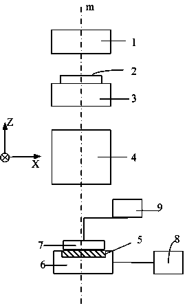
[0025] figure 1 It is a schematic diagram of the structure of the photolithography machine. The lithography machine includes an illumination system 1 , a mask table 3 , a projection objective lens 4 , a rotary table 5 and a workpiece table 6 in sequence along the direction of the geometric center m of the substrate. A mask table 3 carries a mask 2 . The turntable 5 carries a base 7, and the base 7 has more than two marks (not shown in the figure). The turntable 5 drives the base 7 to rotate. The lithography machine also includes an interferometer 8 and an alignment system 9 . The interferometer 8 is connected to the workpiece table 6 for adjusting the position of the workpiece table 6 . The alignment system 9 is used to align the markings on the substrate 7 .

[0026] The method for improving the positioning accuracy of the workpiece tab...


PUM


Abstract

The invention provides a method for improving a positioning precision of a workpiece bench of a lithography machine. According to the method, through a base with an aligning mark pair, acquired data is tested and an actual rotation center of a rotation platform is calculated. Multiple mark pairs are measured so that a circle center position is obtained, an average value is calculated and is used as a final circle center position value of the rotation platform, and in workpiece bench motion, a compensation process is carried out. The method for determination of a rotation center of the rotation platform of the workpiece bench well solves the problem of installation mechanical error-caused misalignment of an actual rotation center of the rotation platform and a geometrical center of the base and the problem of translation interference caused by workpiece bench rotation because of the misalignment. Through compensation of the measured actual rotation center of the rotation platform, a workpiece can be positioned accurately so that exposure quality is greatly improved.

Description

technical field [0001] The invention relates to the technical field of photolithography, in particular to a method for improving the positioning accuracy of a workpiece table of a photolithography machine. Background technique [0002] In the lithography machine, the rotary table is a part of the workpiece table, and it is a component used to realize the Rz movement of the substrate along the Z axis. Due to mechanical errors in the actual installation of the rotary table, the actual rotation center of the workpiece table cannot completely coincide with the design point. At this time, the rotation of the workpiece table will cause crosstalk to the translation, resulting in a deviation in the positioning of the workpiece table, which will affect the final exposure result. If it affects the engraving result, the farther away from the rotation center, the greater the deviation will be. [0003] In the case where the position of the rotation center of the turntable is not tested...

Claims


Application Information

Patent Timeline
Patent Type & Authority Applications(China)
IPC IPC(8): G03F7/20G01B11/00
Inventor 高艳玲王健
Owner SHANGHAI MICRO ELECTRONICS EQUIP (GRP) CO LTD
Why Eureka
Try Eureka