
A simulation test bench for thermal shock and thermal fatigue of heated parts

A technology for simulating test benches and thermal shocks, applied in the field of simulating test benches, can solve problems such as late start, and achieve the effects of improving accuracy, saving test costs, and shortening research and development cycles.

Active Publication Date: 2016-05-25
KUNMING UNIV OF SCI & TECH
View PDF6 Cites 0 Cited by
  • Summary
  • Abstract
  • Description
  • Claims
  • Application Information

AI Technical Summary

Problems solved by technology

[0007] Many typical thermal fatigue and thermal shock simulation test benches have been developed in foreign countries in the 1950s and 1960s, such as the high-frequency induction specimen thermal fatigue test bench developed by the German Mahle company, and the test bench heated by a gas burning flame. However, after the 1980s, there were few relevant materials and reports abroad; while domestic research on simulation test benches started relatively late, and there were few research institutions, only Zhejiang University, Beijing Institute of Technology, A few research universities and research institutions including the Institute of Mechanics of the Chinese Academy of Sciences have carried out relevant work

Method used


Image

  • A simulation test bench for thermal shock and thermal fatigue of heated parts
  • A simulation test bench for thermal shock and thermal fatigue of heated parts
  • A simulation test bench for thermal shock and thermal fatigue of heated parts

Examples


Embodiment 1

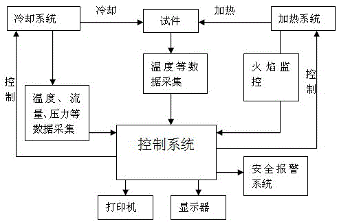
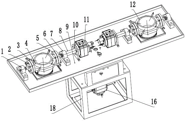
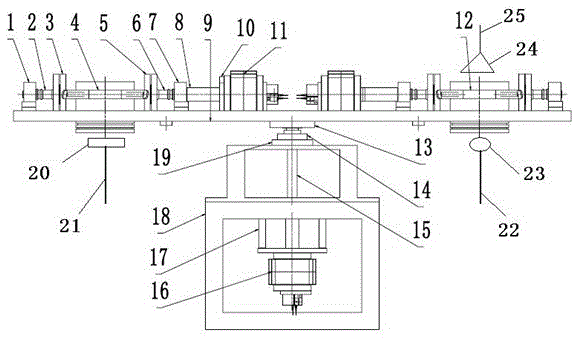
[0035] Embodiment 1: as Figure 1-6 As shown, a simulation test bench for thermal shock and thermal fatigue of heated parts includes a mechanical platform, a heating system, a cooling system, a temperature detection device, a control system, and a safety alarm device; the mechanical platform includes two sets of clamping devices, Heat insulation flange Ⅲ13, bearing with seat 14, main shaft 15, main shaft oscillating cylinder 16, main shaft oscillating cylinder bracket 17, support 18, bearing support 19, the two sets of clamping devices have the same structure and are installed symmetrically about the main shaft 15, and one set of clamping devices The tightening device includes ball bearing with seat Ⅰ1, left shaft 2, heat insulation flange Ⅰ3, clamping mechanism Ⅰ4, heat insulation flange Ⅱ5, right shaft 6, ball bearing with seat Ⅱ7, coupling 8, working platform 9, cylinder Support 10, swing cylinder 11; the ball bearing with seat Ⅰ1 is an interference fit with the left shaft ...

Embodiment 2

[0036] Embodiment 2: as Figure 1-6 As shown, a simulation test bench for thermal shock and thermal fatigue of heated parts includes a mechanical platform, a heating system, a cooling system, a temperature detection device, a control system, and a safety alarm device; the mechanical platform includes two sets of clamping devices, Heat insulation flange Ⅲ13, bearing with seat 14, main shaft 15, main shaft oscillating cylinder 16, main shaft oscillating cylinder bracket 17, support 18, bearing support 19, the two sets of clamping devices have the same structure and are installed symmetrically about the main shaft 15, and one set of clamping devices The tightening device includes ball bearing with seat Ⅰ1, left shaft 2, heat insulation flange Ⅰ3, clamping mechanism Ⅰ4, heat insulation flange Ⅱ5, right shaft 6, ball bearing with seat Ⅱ7, coupling 8, working platform 9, cylinder Support 10, swing cylinder 11; the ball bearing with seat Ⅰ1 is an interference fit with the left shaft ...

Embodiment 3

[0038] Embodiment 3: as Figure 1-6As shown, a simulation test bench for thermal shock and thermal fatigue of heated parts includes a mechanical platform, a heating system, a cooling system, a temperature detection device, a control system, and a safety alarm device; the mechanical platform includes two sets of clamping devices, Heat insulation flange Ⅲ13, bearing with seat 14, main shaft 15, main shaft oscillating cylinder 16, main shaft oscillating cylinder bracket 17, support 18, bearing support 19, the two sets of clamping devices have the same structure and are installed symmetrically about the main shaft 15, and one set of clamping devices The tightening device includes ball bearing with seat Ⅰ1, left shaft 2, heat insulation flange Ⅰ3, clamping mechanism Ⅰ4, heat insulation flange Ⅱ5, right shaft 6, ball bearing with seat Ⅱ7, coupling 8, working platform 9, cylinder Support 10, swing cylinder 11; the ball bearing with seat Ⅰ1 is an interference fit with the left shaft 2...


PUM


Abstract

The invention relates to a simulator test bed for thermal shock and thermal fatigue of parts affected by heat, and belongs to the technical field of test equipment. The simulator test bed for the thermal shock and the thermal fatigue of the parts affected by the heat comprises a mechanical platform, a heating system, a cooling system, a temperature detecting device, a control system and a safety alarm device. The mechanical platform comprises two sets of clamping devices, a heat insulating flange III, a mounted bearing, a main shaft, a main shaft oscillating air cylinder, a main shaft oscillating air cylinder support, a support and a bearing support, and the two sets of clamping devices are identical in structure and are mounted symmetrically relative to the main shaft. According to the simulator test bed for the thermal shock and the thermal fatigue of the parts affected by the heat, the temperature of the surface of a test piece or maximum heating cooling time of the test piece is used as a control condition, two test pieces can be tested at the same time, one test piece is heated, the other test piece is cooled, the simulator test bed for the thermal shock and the thermal fatigue of the parts affected by the heat is simple, practical, high in efficiency, capable of carrying out checking and research on the thermal shock and the thermal fatigue of the test pieces conveniently and fast, and capable of saving cost, shortening research and development cycles and improving accuracy of research.

Description

technical field [0001] The invention relates to a simulation test bench for thermal shock and thermal fatigue of heated components, belonging to the technical field of test equipment. Background technique [0002] With the popularization and application of diesel engine supercharging technology, multi-valve system and other technologies, the degree of strengthening of diesel engines has been continuously improved, and the average effective pressure, speed, and maximum temperature of gas in the cylinder have been continuously increased. Pistons, cylinder heads, exhaust pipes, turbines, cylinders, etc. Heated parts such as sleeves are subject to high thermal stress, and when these heated parts are not made corresponding technical improvements or improperly improved, such as unreasonable structural design, insufficient cooling capacity, insufficient thermal strength of materials, etc., these heated parts will Failure to meet the requirements of use has led to increasingly promi...

Claims


Application Information

Patent Timeline
Patent Type & Authority Patents(China)
IPC IPC(8): G01M13/00G01N3/60
Inventor 雷基林申立中李洪民邓晰文毕玉华贾德文
Owner KUNMING UNIV OF SCI & TECH
Learn More