
Method for evaluating roadbed grouting reinforcement effects

An evaluation method and grouting reinforcement technology, which can be applied in basic structure engineering, basic structure testing, construction, etc., can solve the problems of high cost, inability to evaluate the strength of subgrade, and low detection efficiency, and achieve the effect of avoiding engineering losses.

Active Publication Date: 2014-05-14
天津市市政工程研究院
View PDF5 Cites 6 Cited by
  • Summary
  • Abstract
  • Description
  • Claims
  • Application Information

AI Technical Summary

Problems solved by technology

Among them, the first and second detection methods are non-destructive testing methods, but their detection indicators can only be analyzed qualitatively, and cannot be objectively evaluated from a quantitative perspective.
The third detection method reflects the overall strength of the subgrade and pavement within the depth of the load below the road surface, and cannot evaluate the strength of the subgrade
The detection index of the fourth detection method can be converted into the elastic modulus of subgrade soil, but its detection efficiency is low, and it is greatly dispersed due to the uneven distribution of slurry stones, so it is impossible to make a correct evaluation
The fifth detection method can obtain the physical and mechanical properties of the soil after reinforcement, but it causes great damage to the road surface, and the detection efficiency is low, the cost is expensive, and it cannot be used for large-scale detection.
The results of the detection method in (6) are suitable for the mesoscopic research of roadbed grouting reinforcement soil, and the cost is expensive, so it cannot be used as an actual engineering detection and evaluation method

Method used


Image

  • Method for evaluating roadbed grouting reinforcement effects
  • Method for evaluating roadbed grouting reinforcement effects
  • Method for evaluating roadbed grouting reinforcement effects

Examples


Embodiment Construction

[0031] The present invention will be further described in detail below through the specific examples, the following examples are only descriptive, not restrictive, and cannot limit the protection scope of the present invention with this.

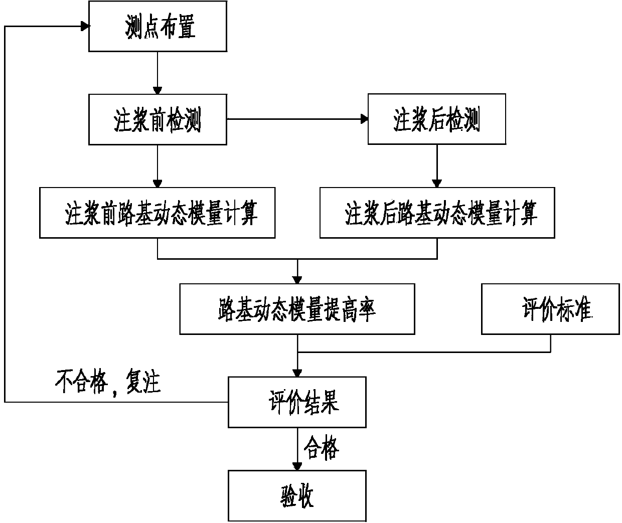
[0032] A method for evaluating roadbed grouting reinforcement effect, the steps of the evaluation method are:

[0033] ⑴. Measuring point layout: On the selected evaluation unit, select a point every 25m along the center line of the two rows of grouting holes as the detection position, and mark the detection position with paint;

[0034] ⑵. Dynamic elastic modulus test of subgrade before grouting:

[0035] The drop weight deflection meter is used to test the above detection positions, and the dynamic elastic modulus E of the subgrade before grouting at each detection position is measured and calculated. i注浆前 ;

[0036] The steps are:

[0037] The drop weight deflection tester adopts 50kN±2.5kN impact load, and the diameter of the bearing ...


PUM


Abstract

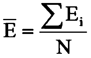
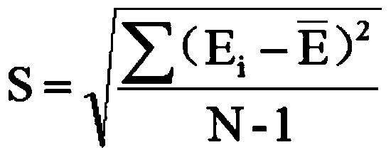
The invention relates to a method for evaluating roadbed grouting reinforcement effects. The method is characterized by comprising steps of (1), arranging measuring points; (2), testing pre-grouting roadbed dynamic elasticity moduli, in other words, testing the various detection positions and acquiring the pre-grouting roadbed dynamic elasticity moduli of the various detection positions by means of computation; (3), testing and acquiring post-grouting roadbed dynamic elasticity moduli; (4), evaluating the grouting reinforcement effects. Representative values E<0> of the roadbed dynamic elasticity moduli of the various measuring points in evaluation units are computed according to formulas, and representative values E<0><pre-grouting> of the pre-grouting roadbed dynamic elasticity moduli and representative value E<0><post-grouting> of the post-grouting roadbed dynamic elasticity moduli are computed, so that increase rates E<0><increase rate> of the roadbed dynamic elasticity moduli can be acquired by means of computation. The method has the advantages that the roadbed dynamic elasticity moduli can be quickly measured on the basis of a falling-weight deflectometer process and are feature parameters which reflect the soil strength of roadbeds, the method is nondestructive, speedy, simple and effective, and accordingly huge engineering loss due to roadbed grouting construction quality defects can be prevented.

Description

technical field [0001] The invention belongs to the technical field of road surface construction, and in particular relates to a roadbed grouting reinforcement effect evaluation method. Background technique [0002] Roadbed grouting reinforcement technology is a new method of roadbed reinforcement, which avoids the "opening and breaking" type of construction. The construction is simple and the reinforcement effect is obvious. It is very important for making full use of the strength of old roads, saving investment, and reducing environmental pollution. economic and social significance. However, since subgrade grouting reinforcement is a hidden project, if quality problems occur, the reinforcement effect will not be achieved, resulting in insufficient subgrade strength, which will lead to early damage to the subgrade and pavement, resulting in huge losses such as rework. In order to ensure the quality of the project and the smooth completion of the project, and to avoid waste...

Claims


Application Information

Patent Timeline
IPC IPC(8): E02D33/00
Inventor 黄桂东肖国良王德群刘永江
Owner 天津市市政工程研究院
Learn More