
Electric pruning shears

A pruning shears, electric technology, used in cutting tools, cutting equipment, gardening and other directions, can solve the problems of burning out the motor, reducing the axial pressure, parts wear, etc., to extend the service life, the braking effect is good, the effect The effect of force equalization

Active Publication Date: 2014-05-14
NINGBO ENERGY POWER TOOLS
View PDF11 Cites 1 Cited by
  • Summary
  • Abstract
  • Description
  • Claims
  • Application Information

AI Technical Summary

Problems solved by technology

Usually, pruning shears have a brake device, this is because for safety reasons, when the cutting blade of the pruning shears is hit by an external force, such as when it hits a rigid object such as barbed wire, the pruning shears themselves will be impacted , after this kind of impact exceeds its allowable load, it will cause damage to the gears, blades and other parts in the pruning shears, and in serious cases, it will burn out the motor in the pruning shears. Therefore, the brake device has a high degree of safety. Requirements, and require easy operation, can stop working quickly after braking
However, the existing braking device of pruning shears has the following disadvantages: because the clutch transmission adopts gear transmission, and in order to protect the motor when subjected to an external force, the gear usually slips. A friction plate and a spring are set between the gear and the shearing part, in other words, the friction plate, the gear, the second friction plate and the spring are connected in sequence and a certain axial pressure is maintained between them, so that the friction plate can pass through However, the friction between the friction plate and the spring will cause the wear of the parts, so that the axial pressure between these parts will gradually decrease, so that the friction force will gradually decrease. In the end, the pruning shears will also slip under the condition of a small external force, so that the pruning shears cannot work normally and reliably

Method used


Image

  • Electric pruning shears
  • Electric pruning shears
  • Electric pruning shears

Examples


Embodiment Construction

[0017] The present invention will be described in further detail below in conjunction with the accompanying drawings and specific embodiments.

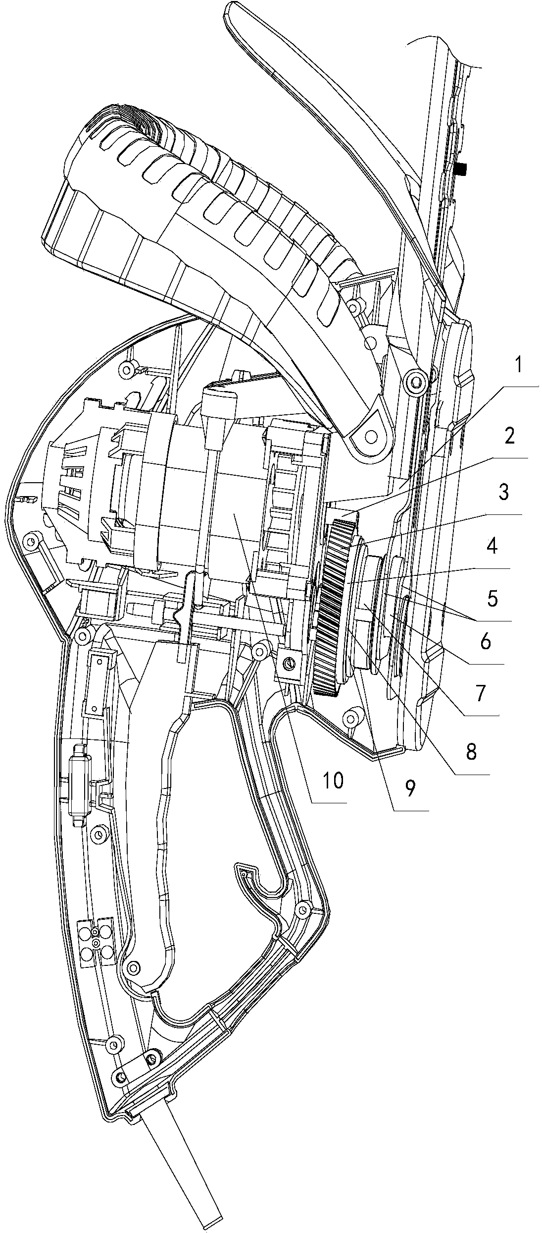
[0018] Depend on Figure 1 to Figure 4 As can be seen from the shown schematic diagram of the structure of the electric pruning shears of the present invention, it includes a casing 1, a motor 10, a transmission and a shear blade 5, the motor 10 is installed in the casing 1, and the output shaft of the motor 10 is connected to the shears by the transmission. Cutting blade 5 is connected. The transmission device includes an input gear 2, an output gear 3 and an eccentric block assembly. The input gear 2 is connected to the output shaft of the motor 10, and the output gear 3 meshed with the input gear 2 is rotatably connected in the casing 1 and passed through the eccentric block assembly. Connect with shear blade 5. Described eccentric block assembly comprises eccentric block 6 and eccentric block cover 11, and one end of eccentric b...


PUM


Abstract

The invention discloses a pair of electric pruning shears. After the side, facing toward a shear blade (5), of an output gear (3) is sequentially connected with an abrasion-resisting plate (4) made of abrasion-resisting engineering plastic, a gasket (8) and a belleville spring (9), and the output gear (3) and the abrasion-resisting plate (4), the abrasion-resisting plate (4) and the gasket (8) as well as the gasket (8) and the belleville spring (9) abut against each other respectively through connection of a locking nut (7) and an eccentric block outer sleeve (11). By the adoption of the structure, the abrasion-resisting plate made of the abrasion-resisting engineering plastic high in abrasion resistance is adopted for being connected with the output gear in a contacting mode, damage to the abrasion-resisting plate caused by friction generated by slipping of the output gear can be reduced, service life can be greatly prolonged, and the speed reducing effect can be achieved within short time.

Description

technical field [0001] The invention relates to the technical field of electric tools, in particular to an electric pruning shear with a braking device. Background technique [0002] At present, with the continuous expansion of urban green area, green belts in parks, highways, and public places have spread all over the country, and because the growth of green plant branches needs to be trimmed frequently to be orderly and stylish, electric pruning shears are getting more and more popular. increasingly applied. The electric pruning shears in the prior art are mainly composed of a main body and a shearing machine. Parts include shear blades. The motor is connected to the connecting piece that drives the movement of the shearing blade through a clutch device, and the clutch device usually adopts a transmission mode of gear meshing. Usually, pruning shears have a brake device, this is because for safety reasons, when the cutting blade of the pruning shears is hit by an extern...

Claims


Application Information

Patent Timeline
IPC IPC(8): A01G3/033
Inventor 朱景宽杨文庆
Owner NINGBO ENERGY POWER TOOLS
Learn More