
Electric capstan

A technology of electric winches and transmission shafts, which is applied in the direction of mechanical drive clutches, couplings and brakes, clutches that mesh with each other, etc., and can solve damage, insufficient width of the third-stage sun gear and the second-stage planet carrier, and failure of the winch Use and other problems to achieve the effect of improving the use effect and braking effect

Active Publication Date: 2020-02-04
ZHEJIANG RUNVA MECHANICAL & ELECTRICAL
View PDF9 Cites 0 Cited by
  • Summary
  • Abstract
  • Description
  • Claims
  • Application Information

AI Technical Summary

Problems solved by technology

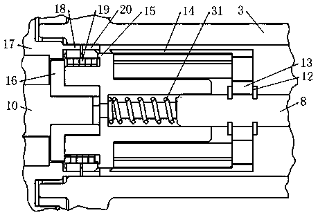
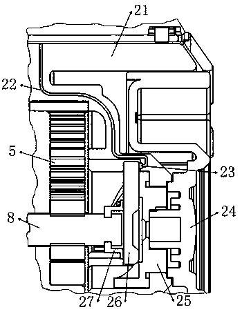
But when the user forgets to pull the twisted rope, and when the elastic recovery force of the compression spring at the coupling becomes smaller after long-term use, the speed at which the third-stage sun gear enters the second-stage planetary carrier becomes slower. When the motor drives the inner teeth of the second-stage planet carrier to contact the outer teeth of the entering third-stage sun gear and start transmission, it is very likely that the third-stage sun gear has not been inserted in place; because the third-stage sun gear and the second-stage planetary There is pressure in the meshing of the teeth between the racks to generate friction. The insufficient thrust of the compression spring will inevitably lead to insufficient meshing width between the third-stage sun gear and the second-stage planetary carrier. If this state is used for a long time, the third-stage sun gear and the second-stage planet carrier The teeth of the planet carrier must be damaged, which will cause the winch to be unable to use normally

Method used


Image

  • Electric capstan
  • Electric capstan
  • Electric capstan

Examples


Embodiment Construction

[0039] The present invention will be described below with reference to the accompanying drawings; however, it should be understood that the structural proportions in the accompanying drawings are only exemplary and not intended to limit the scope of the present disclosure.

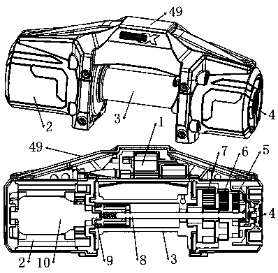
[0040] An electric winch, such as figure 1 As shown, it includes an outer shell 49, an electric control module 1 is housed in the upper side of the outer shell 49, a motor module 2 is housed in the left end side of the outer shell 49 and a deceleration module and a clutch 4 are housed in the right end side, and a middle part of the lower side of the outer shell 49 is equipped with Drum 3, the motor 10 in the motor module 2 drives the transmission shaft 8 located in the drum 3 to rotate through the brake unit 9, the transmission shaft 8 drives the rotation of the drum 3 through the deceleration module, and the clutch 4 controls the axial movement of the transmission shaft 8; the above deceleration The modul...


PUM


Abstract

The invention belongs to the capstan field, and particularly relates to an electric capstan. The electric capstan comprises an electric control module, a motor module, a roller, a clutch, a first-level speed reduction assembly, a second-level speed reduction assembly, a third-level speed reduction assembly, a transmission shaft and a braking unit. A pressure inductor can recognize whether a third-level sun gear and a second-level planet carrier are completely engaged or not. After the third-level sun gear and the second-level planet carrier are completely engaged, a motor is started so that the capstan can be normally used. A friction block A and a friction block B are designed to conduct friction braking with a friction ring A and a friction ring B, so that braking is established betweenthe transmission shaft and the friction ring at the support position and between the transmission shaft and the friction ring at the roller position, and a better braking effect is achieved. When a coupler A and a coupler B relatively move, a rectangular spring can deform and rub with the friction block A and the friction block B, heat generated due to friction is little, and influences generateddue to rectangular spring failures can be neglected. Accordingly, the service life of the rectangular spring can be prolonged.

Description

technical field [0001] The invention belongs to the field of winches, in particular to an electric winch. Background technique [0002] At present, in the winches in the existing field, the braking unit in the winch is to establish a brake between the intermediate transmission shaft and the friction ring at the bracket, or to establish a brake between the intermediate transmission shaft and the drum; The braking scheme of the company's winch is to brake the intermediate transmission shaft and the drum; through the innovation and improvement of the braking unit, the braking can be established between the intermediate transmission shaft and the friction ring at the bracket and the drum respectively to achieve more Good braking effect. [0003] In addition, in the winch in the existing field, the principle of the power connection or clutch realized by the deceleration assembly and the intermediate transmission shaft in the winch is: the clutch is realized by changing the meshi...

Claims


Application Information

Patent Timeline
IPC IPC(8): B66D1/22B66D1/12B66D1/46B66D5/08F16D47/02F16D67/02
CPCB66D1/14B66D1/7447B66D1/7484B66D5/08F16D11/16F16D47/02F16D67/02F16D2011/004
Inventor 俞芷琳戴林吉张小彬叶岭
Owner ZHEJIANG RUNVA MECHANICAL & ELECTRICAL
Learn More