Zero-voltage switching pulse-width modulation converter
A pulse width modulation, converter technology, applied in the conversion device for adjusting electrical variables, output power, converting DC power input to DC power output, etc., can solve converter failure, temperature rise, large loss of auxiliary circuit devices, etc. question
- Summary
- Abstract
- Description
- Claims
- Application Information
AI Technical Summary
Problems solved by technology
Method used
Image
Examples
Embodiment 1
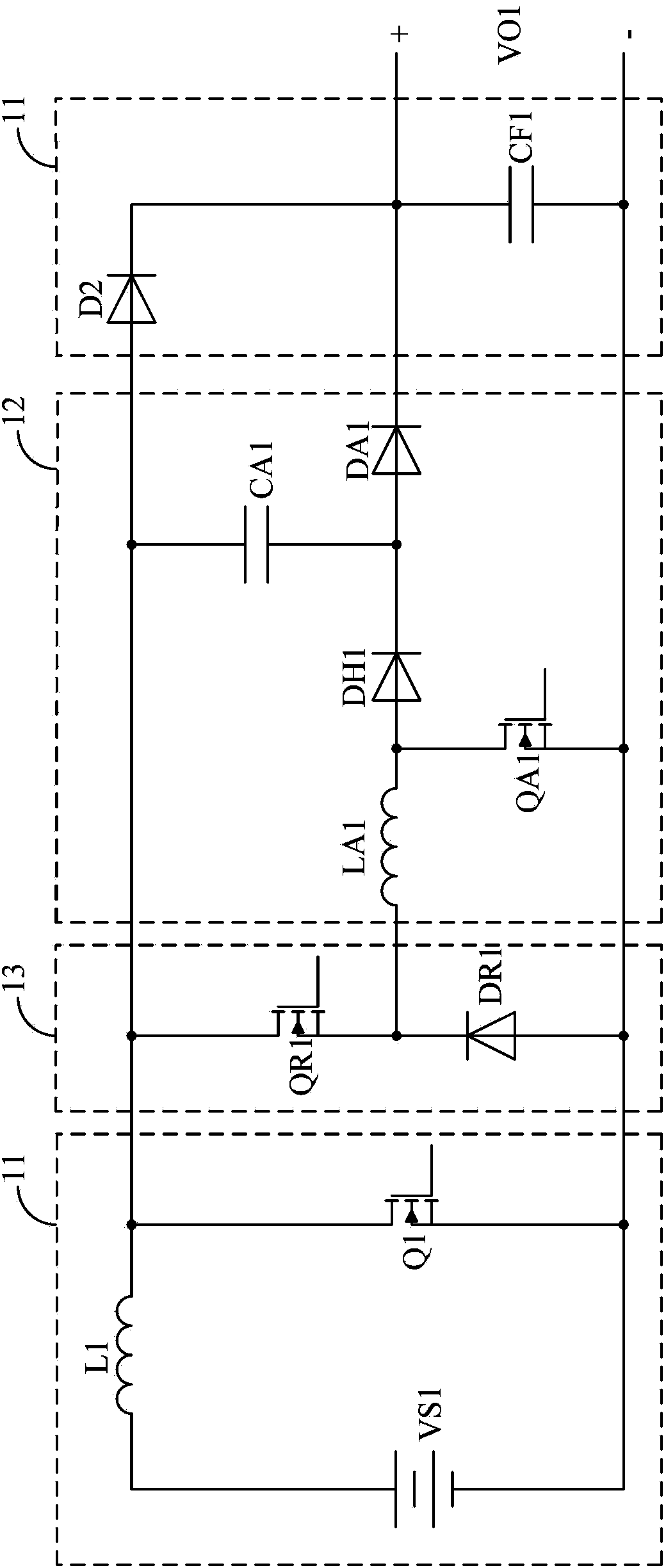
[0043] image 3 The circuit of the zero-voltage conversion pulse width modulation converter provided by the first embodiment of the present invention is shown, and the zero-voltage conversion pulse width modulation converter is a Boost type zero-voltage conversion pulse width modulation converter.
[0044]Specifically, in the Boost-type zero-voltage conversion PWM converter, the main circuit 11 may include: a first input power supply VS1 of the zero-voltage conversion PWM converter, a first main switch Q1, a first main inductor L1, The first main diode D2 and the first filter capacitor CF1. The first end of the first main inductance L1 is connected to the positive pole of the first input power supply VS1, the second end of the first main inductance L1 is connected to the high end of the first main switch tube Q1 and the anode of the first main diode D2. The low end of the switch tube Q1 is connected to the negative pole of the first input power supply VS1, and the low end of ...
Embodiment 2
[0055] Figure 4 The circuit of the zero-voltage conversion pulse width modulation converter provided by the second embodiment of the present invention is shown. The zero voltage conversion pulse width modulation converter is a Boost zero voltage conversion pulse width modulation converter.
[0056] and image 3 Different from what is shown, the Boost zero-voltage conversion PWM converter does not include the first buffer diode DH1 and the first auxiliary capacitor CA1. That is to say, the auxiliary circuit 12 at this time includes: a first auxiliary inductor LA1, a first auxiliary switch transistor QA1, and a first auxiliary diode DA1. The first end of the first auxiliary inductance LA1 is connected to the reset circuit 13, the second end of the first auxiliary inductance LA1 is connected to the high end of the first auxiliary switch QA1 and the anode of the first auxiliary diode DA1. The low end is connected to the reset circuit 13 and the low end of the first main switch...
Embodiment 3
[0059] Figure 5 The circuit of the zero-voltage conversion pulse width modulation converter provided by the third embodiment of the present invention is shown, and the zero-voltage conversion pulse width modulation converter is a Buck-type zero-voltage conversion pulse width modulation converter.
[0060] Specifically, in the Buck-type zero-voltage conversion PWM converter, the main circuit 11 may include: a second input power supply VS2 of the zero-voltage conversion PWM converter, a second main switch Q2, a second main inductor L2, The second main diode D3 and the second filter capacitor CF2. The high end of the second main switch tube Q2 is connected to the positive pole of the second input power supply VS2, the auxiliary circuit 12 and the reset circuit 13, and the low end of the second main switch tube Q2 is connected to the reset circuit 13, the auxiliary circuit 12, and the second main inductance L2. The first end of the second main diode D3 and the cathode of the sec...
PUM
 Abstract
Description
Claims
Application Information
 - R&D
- Intellectual Property
- Life Sciences
- Materials
- Tech Scout
- Unparalleled Data Quality
- Higher Quality Content
- 60% Fewer Hallucinations
Browse by: Latest US Patents, China's latest patents, Technical Efficacy Thesaurus, Application Domain, Technology Topic, Popular Technical Reports.
© 2025 PatSnap. All rights reserved.Legal|Privacy policy|Modern Slavery Act Transparency Statement|Sitemap|About US| Contact US: help@patsnap.com


