
Package substrate and method of forming the same

A technology for packaging substrates and manufacturing methods, which is applied in semiconductor/solid-state device manufacturing, electrical components, electrical solid-state devices, etc., and can solve difficult alignment of laser openings, poor electrical connection of conductive silicon vias 100, and conductive silicon vias 100 layout. Problems such as difficulty in increasing density

Inactive Publication Date: 2014-05-07
IND TECH RES INST +1
View PDF3 Cites 0 Cited by
  • Summary
  • Abstract
  • Description
  • Claims
  • Application Information

AI Technical Summary

Problems solved by technology

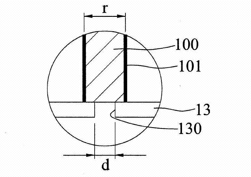
[0007] However, because the diameter of the conductive TSVs 100 is too large, it is difficult to increase the layout density of the conductive TSVs 100 in the silicon interposer 10.
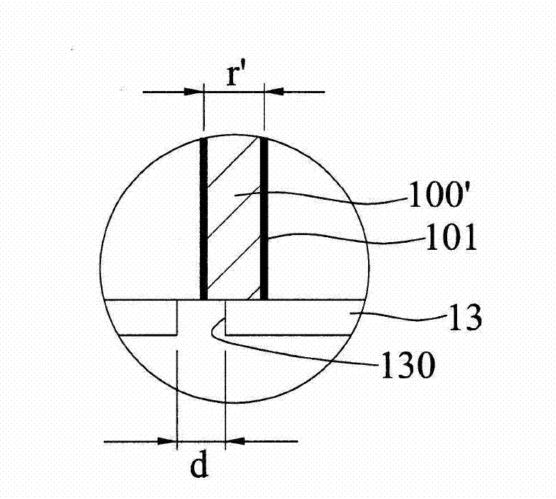
[0008] In addition, if the end surface diameter r' of the conductive TSV 100' is to be less than 80 μm (eg, 50 μm) in order to increase the layout density and reduce the cost, it will be difficult to align the laser hole, that is, the position of the blind hole 130 cannot be completely located above the end surface of the conductive TSV 100 ′, such as figure 1 As shown in ", the conductive blind via 140 contacts the silicon material of the silicon interposer 10, and the electrical connection with the conductive TSV 100 is poor.

Method used


Image

  • Package substrate and method of forming the same
  • Package substrate and method of forming the same
  • Package substrate and method of forming the same

Examples


Embodiment Construction

[0067] The implementation of the present disclosure is described below through specific specific examples, and those skilled in the art can easily understand other advantages and effects of the present disclosure from the content disclosed in this specification.

[0068] It should be noted that the structures, proportions, sizes, etc. shown in the drawings attached to this specification are only used to match the content disclosed in the specification for the understanding and reading of those skilled in the art, and are not intended to limit the scope of this disclosure. Therefore, it has no technical significance. Any modification of structure, change of proportional relationship or adjustment of size shall still fall within the scope of The technical content disclosed in this disclosure must be within the scope covered. At the same time, terms such as "above", "first", "second" and "one" quoted in this specification are only for the convenience of description, and are not u...


PUM

PropertyMeasurementUnit
Diameteraaaaaaaaaa
End diameteraaaaaaaaaa
Diameteraaaaaaaaaa

Abstract

A package substrate and a method for forming the package substrate are disclosed. The package substrate includes an interposer having a plurality of conductive through vias and a first insulating layer formed on the sidewalls of the conductive through vias, a second insulating layer formed on one side of the interposer, and a plurality of conductive vias formed in the second insulating layer and electrically connected to the conductive through vias. By increasing the thickness of the first insulating layer, the face diameter of the conductive through vias can be reduced, and the layout density of the conductive through vias in the interposer can thus be increased.

Description

technical field [0001] The present disclosure relates to a package substrate, in particular to a package substrate embedded with an interposer and a manufacturing method thereof. Background technique [0002] As electronic products become thinner, thinner and smaller, and their functions are continuously improved, the wiring density of the chip is getting higher and higher, and the unit of nanometer size, so the distance between the contacts on the chip is extremely small. However, at present, the pitch of the electrical contacts of the flip-chip package substrate is in the unit of micrometers, so it cannot be effectively reduced to the size corresponding to the pitch of the chip contacts. As a result, although there are semiconductor chips with high circuit density, there are no compatible chips. Encapsulate the substrate so that it cannot effectively produce electronic products. [0003] In order to overcome the above problems, a silicon interposer (Silicon interposer) is...

Claims


Application Information

Patent Timeline
IPC IPC(8): H01L23/498H01L21/48
CPCH01L23/49816H01L23/49822H01L23/49827H01L2224/16225H01L2924/15174H01L2924/15311
Inventor 陈裕华骆韦仲胡迪群谢昌宏
Owner IND TECH RES INST
Learn More