Rotation type multifunctional bottom tooth spring piece mechanism
A multi-functional, rotating technology, applied in the direction of mechanically driven clocks, instruments, clockwork protection, etc., can solve the problems of difficulty in obtaining consistent precision dimensions, fatigue resistance, inelasticity or low elasticity, etc., and achieve a clear and pleasant rotating sound , Improve accuracy, easy processing effect
- Summary
- Abstract
- Description
- Claims
- Application Information
AI Technical Summary
Problems solved by technology
Method used
Image
Examples
Embodiment Construction
[0033] In order to further illustrate the principle and structure of this patent, the preferred embodiments of this patent are now described in detail in conjunction with the accompanying drawings, but the embodiments are only for illustration and explanation, and cannot be used to limit the scope of protection of this patent.
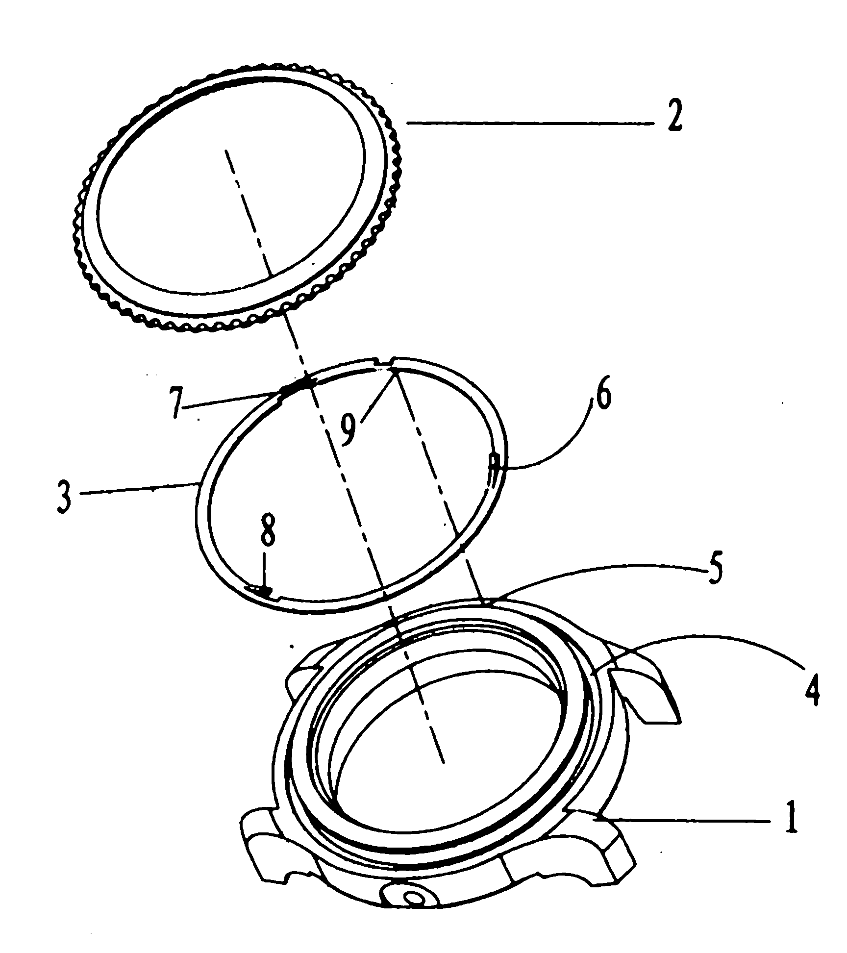
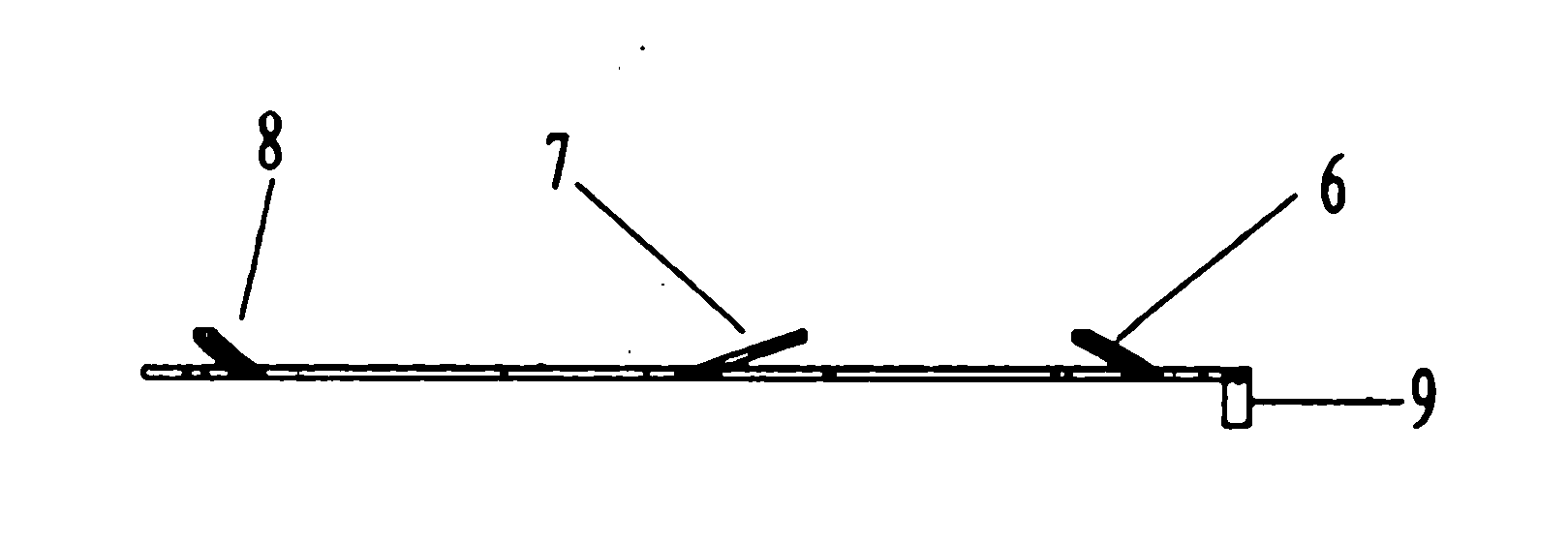
[0034] as attached Figure 4 , attached Figure 5 , attached Image 6 As shown, it includes a watch case plate 1, a rotating bezel cover 2 and a rotating multi-function bottom teeth shrapnel 3, the upper surface of the watch case plate 1 forms a receiving groove 4 and a round fixing hole 5, The fixed point 7 of the rotating multi-functional bottom teeth shrapnel 3 is fixed in the circular fixing hole 5 on the bottom plane of the accommodation groove 4, and the rotating bezel cover 2 is placed on the accommodation groove 4, so that The rotating multi-function elastic piece 3 is located between the case plate 1 and the rotating bezel cover 2, the secti...
PUM
 Abstract
Description
Claims
Application Information
 - R&D
- Intellectual Property
- Life Sciences
- Materials
- Tech Scout
- Unparalleled Data Quality
- Higher Quality Content
- 60% Fewer Hallucinations
Browse by: Latest US Patents, China's latest patents, Technical Efficacy Thesaurus, Application Domain, Technology Topic, Popular Technical Reports.
© 2025 PatSnap. All rights reserved.Legal|Privacy policy|Modern Slavery Act Transparency Statement|Sitemap|About US| Contact US: help@patsnap.com


