
Mechanical evaporator

An evaporator and mechanical technology, applied in evaporation, chemical instruments and methods, heating water/sewage treatment, etc., can solve the problems of low efficiency and achieve the effect of improving the evaporation process and reducing costs

Active Publication Date: 2014-05-07
BEIJING HORIZON ENVIRONMENTAL TECH
View PDF4 Cites 4 Cited by
  • Summary
  • Abstract
  • Description
  • Claims
  • Application Information

AI Technical Summary

Problems solved by technology

The natural evaporation method of building evaporation ponds is limited by the land supply and the cost of building storage ponds, and the efficiency is very low

Method used


Image

  • Mechanical evaporator
  • Mechanical evaporator
  • Mechanical evaporator

Examples


Embodiment 1

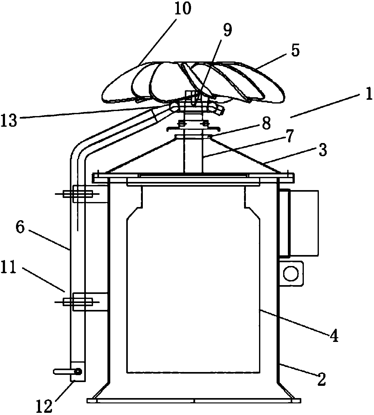
[0017] refer to figure 1 , a mechanical evaporator 1 of the present invention, which can be fixed on a bracket (not shown) for use, includes a casing 2, a top cover 3, a motor 4, an impeller device 5 and a water inlet device 6; the motor 4 includes a transmission shaft 7; the top cover 3 has an opening 8, and the top cover 3 is fixed on the casing 2; the impeller device 5 includes a hub 9 and a plurality of blades 10 fixed to the hub 9; the motor 4 passes through the top cover through a transmission shaft 7 3 to connect the hub 9 to drive the blade 10 to rotate, the water inlet device 6 includes a water inlet pipe 11, the water inlet pipe 11 includes a water inlet 12 and a water outlet 13, and the water outlet 13 is located below the blade 10.

[0018] During operation, the water inlet 12 supplies water to the water inlet pipe 11 through devices such as a submersible pump (not shown), and the water is sprayed upwards onto the blades 10 from the water outlet 13 of the water inl...

Embodiment 2

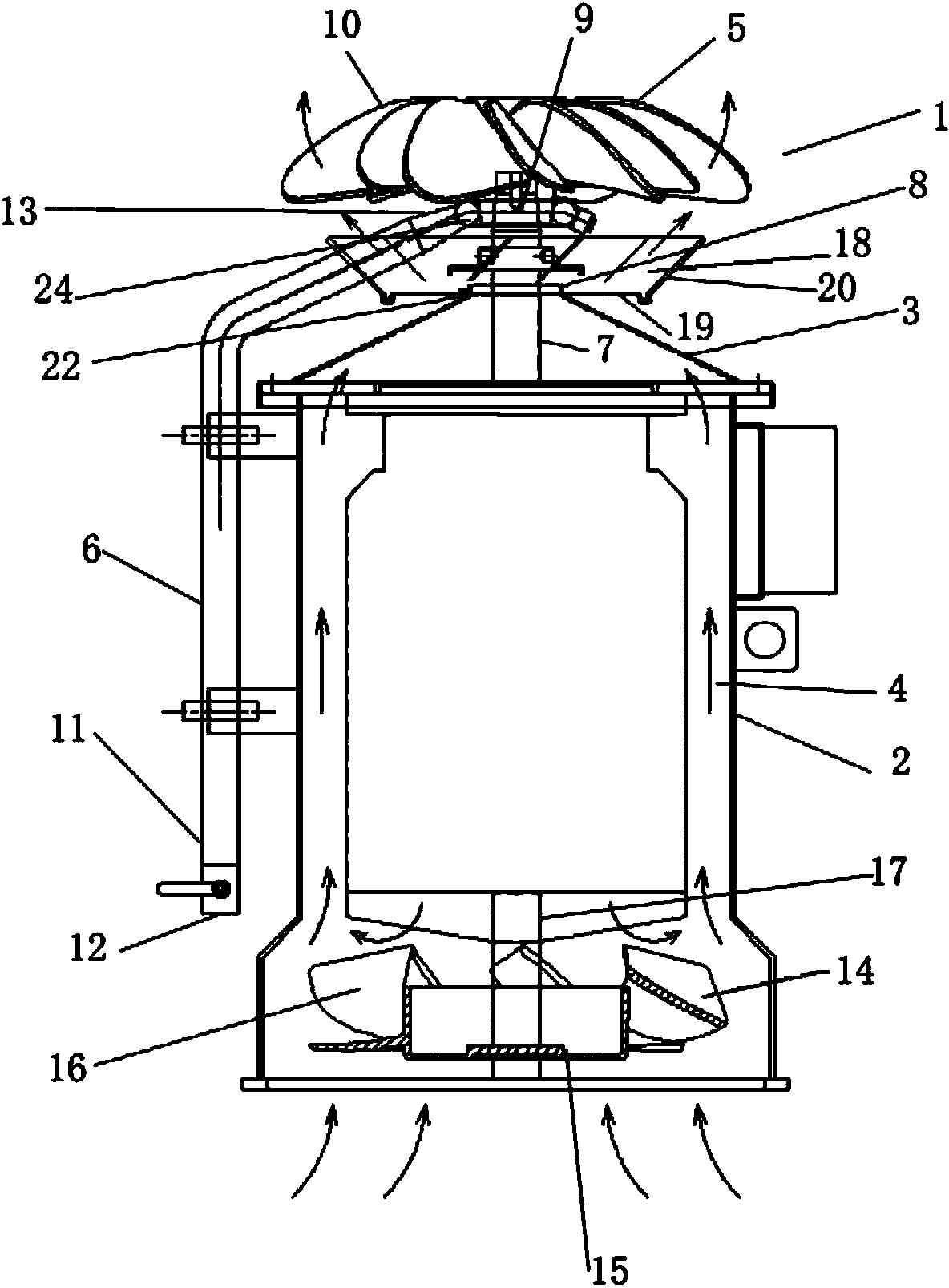
[0020] refer to Figure 2 to Figure 5 , a mechanical evaporator 1 of the present invention, which can be fixed on a bracket (not shown) for use, including a casing 2, a top cover 3, a double-headed motor 4, an impeller device 5 and a water inlet device 6; the double-headed motor 4 includes a transmission shaft 7 at one end and a transmission shaft 17 at the other end; the top cover 3 has an opening 8, and the top cover 8 is fixed on the casing 2; the impeller device 5 includes a hub 9 and a plurality of shafts fixed to the hub 9 The blade 10; the double-head motor 4 passes through the opening 8 of the top cover 3 through the transmission shaft 7 at one end and connects the hub 9 to drive the blade 10 to rotate. The water inlet device 6 includes a water inlet pipe 11, and the water inlet pipe 11 includes a water inlet 12 and The water outlet 13 is located under the blade 10 . The mechanical evaporator 1 includes a hurricane 14 arranged below the double-head motor 4; the openin...


PUM


Abstract

The invention discloses a mechanical evaporator. The mechanical evaporator is characterized by comprising a shell, a top cover, a power device, an impeller device and a water inlet device, wherein the power device comprises a transmission shaft; an opening is formed in the top cover; the top cover is fixed on the shell; the impeller device comprises a hub and a plurality of blades which are fixed on the hub; the power device penetrates through the opening of the top cover through the transmission shaft and is connected with the hub to drive the blades to rotate; the water inlet device comprises a water inlet pipe; the water inlet pipe comprises a water inlet and a water outlet; the water outlet is formed below the blades. According to the mechanical evaporator, the evaporation process can be quickly accelerated. Compared with the efficiency of an evaporation pond, the efficiency of the mechanical evaporator is improved by 10-16 times. The evaporator is relatively compact, reliable and effective, and can be transported to different places; moreover, compared with conventional waste water treatment technologies such as distillation and dialysis, the mechanical evaporator has the advantage that the cost is greatly reduced.

Description

technical field [0001] The invention relates to an evaporator, in particular to a mechanical evaporator for treating waste water. Background technique [0002] Evaporation is an applied technology for treating large volumes of wastewater. The natural evaporation method of building evaporation ponds is limited by the land supply and the cost of building storage ponds, and the efficiency is very low. [0003] Therefore, how to develop a mechanical evaporator that can effectively treat a large amount of waste water has been devoted to research and development by those skilled in the art. Contents of the invention [0004] The purpose of the present invention is to provide a mechanical evaporator to improve evaporation efficiency. [0005] Therefore, the present invention provides a mechanical evaporator, which is characterized in that: the mechanical evaporator includes a casing, a top cover, a power device, an impeller device and a water inlet device; the power device incl...

Claims


Application Information

Patent Timeline
Patent Type & Authority Applications(China)
IPC IPC(8): B01D1/00C02F1/04
Inventor 田旭峰
Owner BEIJING HORIZON ENVIRONMENTAL TECH
Learn More