
Method and system for designing distributed virtual network in cloud calculating data center

A data center, virtual network technology, applied in the field of cloud computing, can solve the problems of unpopular, expensive, and inflexible control plane of distributed virtual switches.

Inactive Publication Date: 2014-04-30
INSPUR BEIJING ELECTRONICS INFORMATION IND
View PDF2 Cites 64 Cited by
  • Summary
  • Abstract
  • Description
  • Claims
  • Application Information

AI Technical Summary

Problems solved by technology

[0004] At present, distributed virtual switches are not popular in cloud data centers. The common distributed virtual switches are basically vmware and citrix, and both of them need to pay expensive prices to use. For many small and medium-sized enterprises and users, how to build a It is urgent and difficult to implement an inexpensive distributed virtual switching network to meet the increasingly complex network management of cloud data centers
[0005] Software-defined networking (SDN, Software-defined networking) separates the control plane of network equipment from embedded nodes to the software platform, and the network architecture is automatically controlled by the software-driven controller (Controller). It replaces the traditional embedded-based A control plane that is not flexible enough; software-defined networking is a new network control plane implementation method, which meets the network requirements of reducing network complexity, virtualization, and cloud computing. A software-defined and controllable Internet, in addition to being more flexible, Through appropriate control algorithms, the robustness, operating efficiency and security of the network itself will be greatly improved; at present, there is no effective implementation plan for the construction of a distributed virtual network based on SDN cloud computing data center

Method used


Image

  • Method and system for designing distributed virtual network in cloud calculating data center
  • Method and system for designing distributed virtual network in cloud calculating data center
  • Method and system for designing distributed virtual network in cloud calculating data center

Examples


Embodiment Construction

[0021] Hereinafter, the present invention will be described in detail with reference to the drawings and examples. It should be noted that, in the case of no conflict, the embodiments in the present application and the features in the embodiments can be combined with each other.

[0022] The invention provides a method for designing a distributed virtual network of a cloud computing data center, comprising the following steps:

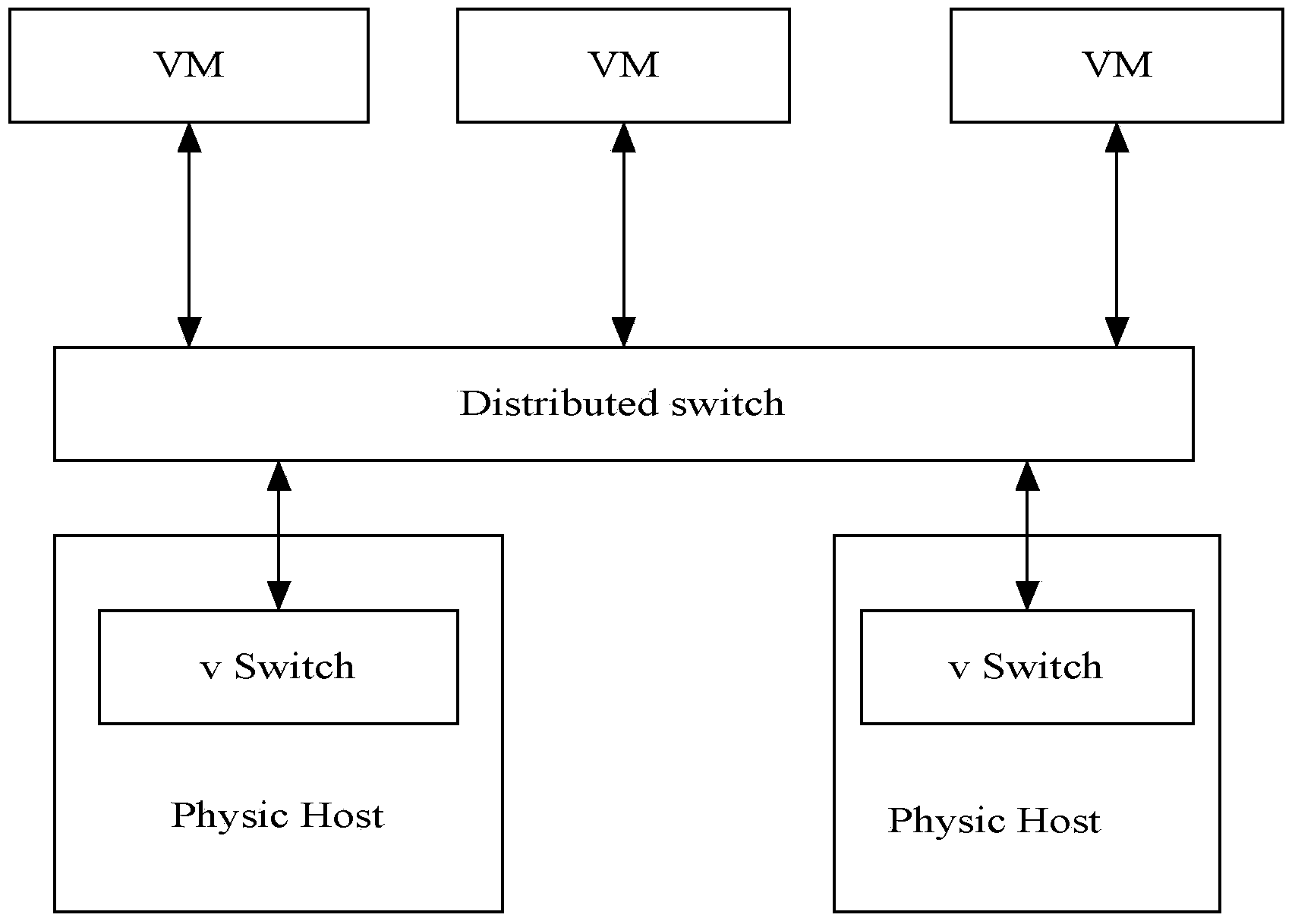
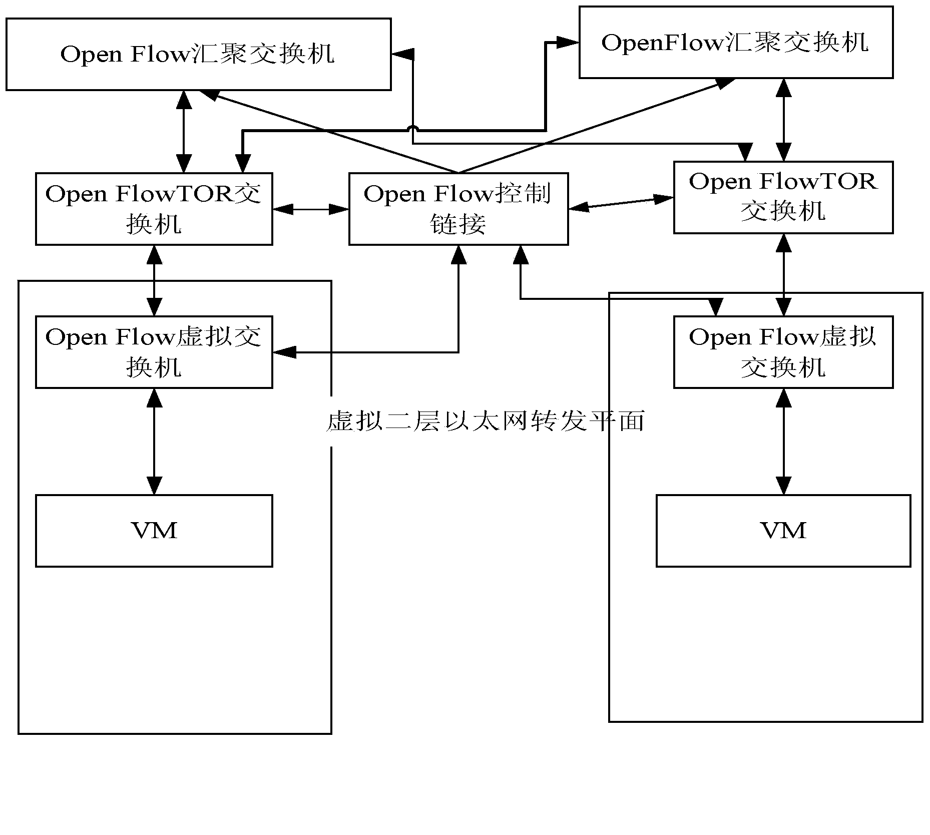
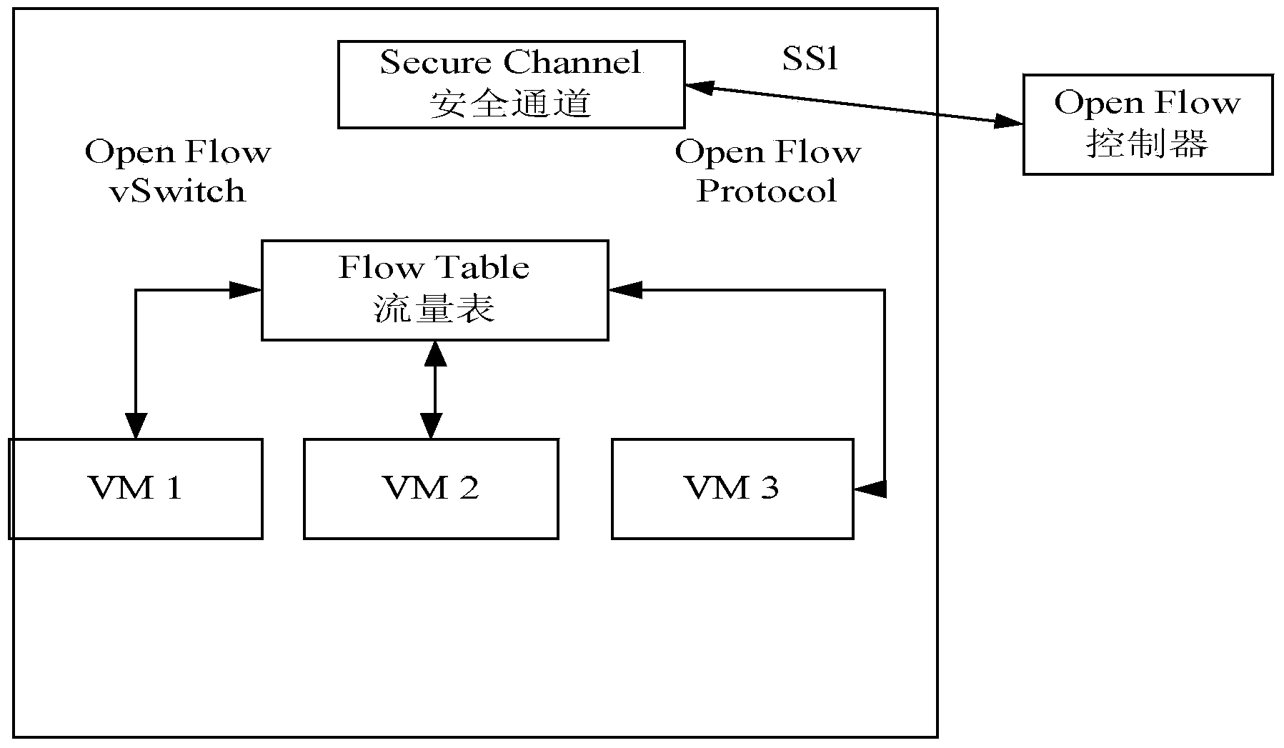
[0023] Create a distributed virtual switch, wherein the distributed virtual switch is made up of multiple Openflow virtual switches, OpenFlow controllers, and physical switch ports;

[0024] The Openflow virtual switch communicates with the OpenFlow controller according to a preset policy.

[0025] Among them, the process of creating a distributed virtual switch is:

[0026] Issue the command to create a distributed virtual switch through the client segment of the data center, and call the vCenter interface to create distributed virtual switch inform...


PUM


Abstract

The invention provides a method and system for designing a distributed virtual network in a cloud calculating data center. The method and system are applied to the technical field of cloud calculation. The method includes the following steps: creating a distributed virtual switch, wherein the distributed virtual switch is composed of a plurality of OpenFlow virtual switch bodies, an OpenFlow controller and a physical switch port; enabling the OpenFlow virtual switch bodies to be in communication with the OpenFlow controller according to preset strategies. According to the method, the distributed virtual switch is created based on the SDN thought and particularly achieved through the OpenFlow protocol. The whole data center is configured by the distributed virtual switch in a concentrated mode through the OpenFlow controller, virtual switch networking is accordingly simplified, and centralized management and intelligent monitoring on the virtual network environment in the cloud calculating data center are achieved.

Description

technical field [0001] The invention relates to the technical field of cloud computing, in particular to a method and system for designing a distributed virtual network of a cloud computing data center. Background technique [0002] The virtual switch is an important software entity in the cloud computing data center, which interconnects the virtual machines, physical hosts and physical network devices in the data center to form a huge virtual resource pool; the virtual switch is responsible for transmitting data to the destination address, detecting The flow of data packets on the network, and the establishment of intelligent connection sessions. [0003] Virtual switches can be divided into standard virtual switches and distributed virtual switches. Their essential difference lies in the scope of their applications: standard virtual switches can only be applied to one physical host without any flexibility, and other hosts cannot share a virtual switch; The distributed vir...

Claims


Application Information

Patent Timeline
IPC IPC(8): H04L29/08
Inventor 罗登亮颜秉珩
Owner INSPUR BEIJING ELECTRONICS INFORMATION IND
Learn More