Gas discharge tube

A technology of gas discharge tube and discharge tube, which is applied in the direction of solid cathode components, etc., can solve the problems of high welding process level requirements, slow response speed, and weak flow capacity, so as to reduce the layout area and space and increase the arc voltage value , Improve the effect of flow capacity

Active Publication Date: 2014-04-30
SHENZHEN BENCENT ELECTRONICS CO LTD
View PDF5 Cites 6 Cited by
  • Summary
  • Abstract
  • Description
  • Claims
  • Application Information

AI Technical Summary

Problems solved by technology

[0004] The embodiment of the present application provides a gas discharge tube, which not only solves the problems of slow response speed, low arc pressure, and weak flow capacity of the existing gas discharge tube, but also solves the difficulty in layout and processing when the existing gas discharge tube is applied to products. Problems of low efficiency and high requirements for welding technology

Method used


Image

  • Gas discharge tube
  • Gas discharge tube
  • Gas discharge tube

Examples


Embodiment Construction

[0056] The following will clearly and completely describe the technical solutions in the embodiments of the application with reference to the drawings in the embodiments of the application. Apparently, the described embodiments are only some of the embodiments of the application, not all of them. Based on the embodiments in this application, all other embodiments obtained by persons of ordinary skill in the art without making creative efforts belong to the scope of protection of this application.

[0057] In the following, specific examples will be used to describe in detail respectively.

[0058] See Figure 4 , Figure 4 The structural diagram of another kind of gas discharge tube provided for the embodiment of the present invention; Figure 4 In the illustrated embodiment, the gas discharge tube provided in this embodiment includes a discharge tube body 41 and an overvoltage protection plate 42, and the discharge tube body 41 includes two terminal electrodes, respectively...


PUM


Abstract

The invention provides a gas discharge tube. The gas discharge tube comprises a discharge tube body and an overvoltage protective board, wherein a plurality of voltage-limiting components are arranged inside the overvoltage protective board or on the outer surface of the overvoltage protective board, the number of the voltage-limiting components is equal to that of intermediate electrodes, and the voltage-limiting components are electrically connected with the intermediate electrodes in a one-to-one mode. The protection effect is better, the response speed is higher, and reliability is higher. The discharge tube body and the overvoltage protective board are electrically connected and are integrated together, and when the gas discharge tube is applied to an overvoltage protection circuit, the working procedure of welding of the voltage-limiting components is omitted; when the gas discharge tube is applied, the welding technology is simple, processing is easier and more convenient, processing efficiency is improved, the layout area and the space of a whole circuit board are reduced, and layout of the circuit board can be conveniently and reasonably planned.

Description

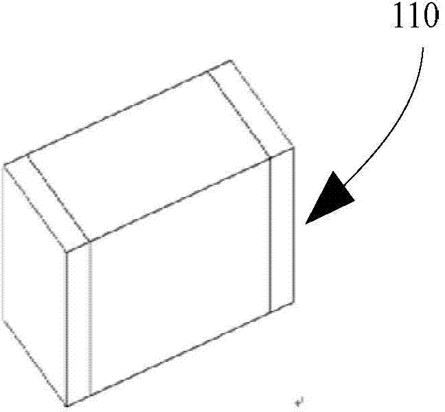
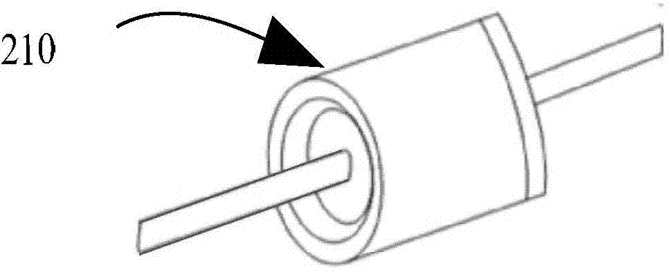
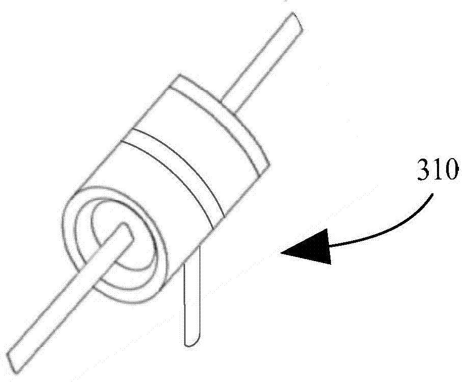
technical field [0001] The application belongs to the technical field of overvoltage protection, and in particular relates to a gas discharge tube. Background technique [0002] In the field of overvoltage protection technology, ceramic gas discharge tubes and semiconductor discharge tubes are often used in the first or first two stages of multi-level protection circuits to discharge lightning transient overcurrent and limit overvoltage. Existing gas discharge tubes include patch discharge tubes, plug-in diode discharge tubes and plug-in three-electrode discharge tubes. The structure of existing patch discharge tubes can refer to figure 1 For the gas discharge tube 110 shown, the structure of the existing plug-in diode discharge tube can refer to figure 2 The gas discharge tube 210 shown, the structure of the existing plug-in triode discharge tube can refer to image 3 A gas discharge tube 310 is shown. The working principle of the above three gas discharge tubes is to r...

Claims


Application Information

Patent Timeline
Patent Type & Authority Applications(China)
IPC IPC(8): H01J17/34H01J17/02
Inventor 周垠群蔡锦波王久骆建辉高桂丽
Owner SHENZHEN BENCENT ELECTRONICS CO LTD
Why Eureka
Try Eureka