
Method and device for controlling material drying temperature of cement production line with waste heat power generation

A technology of drying temperature and waste heat power generation, which is applied in cement production, drying, drying machines, etc., can solve the problems of reduced output, unstable cement quality, and increased energy consumption of cement clinker, so as to improve output and quality, The effect of maintaining stable operation and reducing the difficulty of operation

Inactive Publication Date: 2014-04-30
娄卡奔新能源科技发展(上海)有限公司
View PDF0 Cites 1 Cited by
  • Summary
  • Abstract
  • Description
  • Claims
  • Application Information

AI Technical Summary

Problems solved by technology

However, waste heat power generation is an auxiliary section of the cement clinker line, and it is impossible to operate independently like a traditional power station, because the heat source for power generation comes from the waste gas of the clinker cement line, and the waste gas after power generation is likely to dry materials, and the current domestic The external situation is that the cement clinker equipment and the waste heat power generation equipment are basically independent of each other, and they operate in isolation and are not interlocked. The clinker cement operator and the waste heat power generation operator are also independent of each other and do their own thing. Unstable quality, decreased output, increased energy consumption of cement clinker, unstable cement quality, decreased output, etc.

Method used


Image

  • Method and device for controlling material drying temperature of cement production line with waste heat power generation
  • Method and device for controlling material drying temperature of cement production line with waste heat power generation
  • Method and device for controlling material drying temperature of cement production line with waste heat power generation

Examples


Embodiment Construction

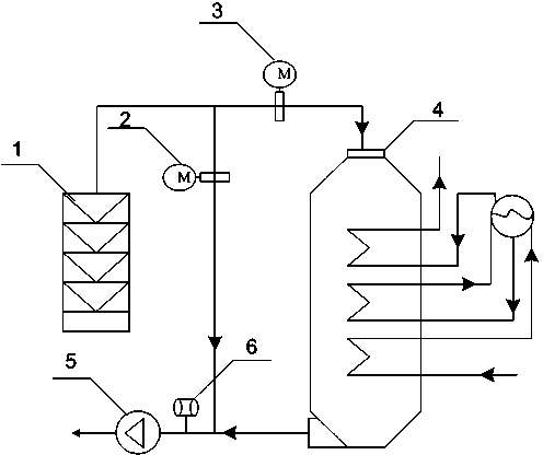
[0018] exist figure 1 In the process, the electric louver valve 2 is installed in the exhaust gas bypass pipeline at the kiln tail, the electric louver valve 3 is installed in the exhaust gas pipeline at the boiler inlet, and the temperature sensor 6 is installed at the inlet pipeline of the drying system at the kiln tail, and the temperature signal and the opening degree of the electric valve are input and output The signal is connected to the computer control system.

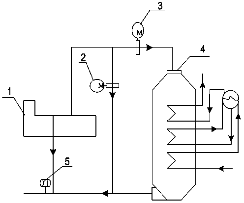
[0019] exist figure 2 In the process, an electric shutter valve 2 is installed in the waste gas bypass pipe of the kiln head, an electric shutter valve 3 is installed in the exhaust gas pipe at the boiler inlet, a temperature sensor 5 is installed at the inlet pipe of the kiln head material drying system, and the temperature signal and the opening degree of the electric valve are input, The output signal is connected to the computer control system.

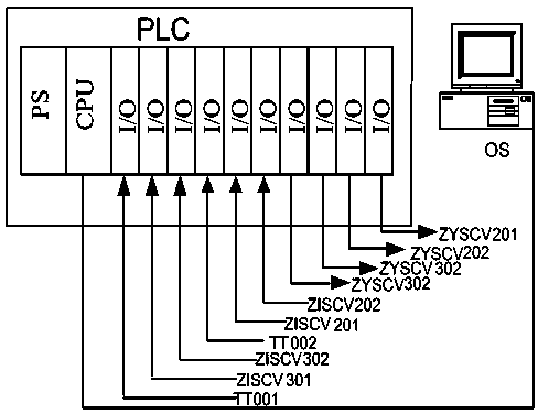
[0020] image 3 Shown is the implementation of the contr...


PUM


Abstract

The invention discloses a method and a device for controlling the material drying temperature of a cement production line with a waste heat power generation. The method is characterized in that the opening of a kiln head and kiln tail bypass waste gas valve is controlled by temperature measured by a temperature sensor mounted at an inlet of a kiln head and kiln tail drying system. The device mainly comprises the temperature sensor, electric louver valves and a computer control system. The temperature sensor is mounted at a drying system inlet waste gas pipeline, one electric louver valve is mounted on a kiln tail waste gas bypass, the other electric louver valve is mounted at a boiler waste gas inlet, temperature signals and valve opening given and feedback signals are accessed to the computer control system, and the computer control system controls the opening of the waste gas bypass valve according to temperature signal change. Compared with past manual adjustment, the control device has the advantages that a clinker line and the waste heat power generation are prevented from fighting over heat sources, stability of a clinker line heat source is ensured, and operation difficulty of operators is reduced.

Description

technical field [0001] The invention relates to air temperature control technology, in particular to a method and device for controlling the drying temperature of materials in a cement production line with waste heat power generation. Background technique [0002] Over the past 30 years of reform and opening up, my country's cement industry has achieved world-renowned achievements. During this period, new dry process cement technology and cement pure low-temperature waste heat power generation have achieved leapfrog development. However, waste heat power generation is an auxiliary section of the cement clinker line, and it is impossible to operate independently like a traditional power station, because the heat source for power generation comes from the waste gas of the clinker cement line, and the waste gas after power generation is likely to dry materials, and the current domestic The external situation is that the cement clinker equipment and the waste heat power generati...

Claims


Application Information

Patent Timeline
IPC IPC(8): F26B21/14F27D17/00C04B7/36
CPCY02P10/25Y02P40/121
Inventor 叶金辉
Owner 娄卡奔新能源科技发展(上海)有限公司
Learn More