Fixed-point quantitative refueling device for car seat chute

A technology for car seats and refueling devices, applied in the direction of quantitative devices, lubricating parts, engine lubrication, etc., can solve the problems of car decoration pollution, grease overflow, insufficient lubrication, etc., achieve high degree of automation, ensure reliability, The effect of easy operation

Inactive Publication Date: 2016-01-20
SHANGHAI INST OF TECH
View PDF9 Cites 0 Cited by
  • Summary
  • Abstract
  • Description
  • Claims
  • Application Information

AI Technical Summary

Problems solved by technology

At present, the manual method of oiling is usually used in China. One method is to put the oil in the oil pot, and the nozzle of the oil pot is aligned with the grooves of the symmetrical chute on both sides of the seat pan of the car seat frame to spray oil point by point; After the brush is stained with oil, paint it in the grooves of the symmetrical chute on both sides under the seat pan of the car seat frame; the above two methods have a low factory pass rate, and the oil volume and oil point cannot be controlled, resulting in symmetrical sides under the seat pan of the car seat frame When the chute is in working condition, the oil quantity and oil points in the groove are unevenly distributed, some parts are not sufficiently lubricated, and the friction force increases. The customer is too hard to use, and the factory index cannot meet the standard. Spillage will cause pollution to the interior decoration of the car, serious waste of grease, and the production efficiency of these two manual oiling methods is low, and the rework rate of inspection before leaving the factory is high

Method used


Image

  • Fixed-point quantitative refueling device for car seat chute
  • Fixed-point quantitative refueling device for car seat chute
  • Fixed-point quantitative refueling device for car seat chute

Examples


Embodiment Construction

[0014] The present invention will be further described below in conjunction with the accompanying drawings and embodiments.

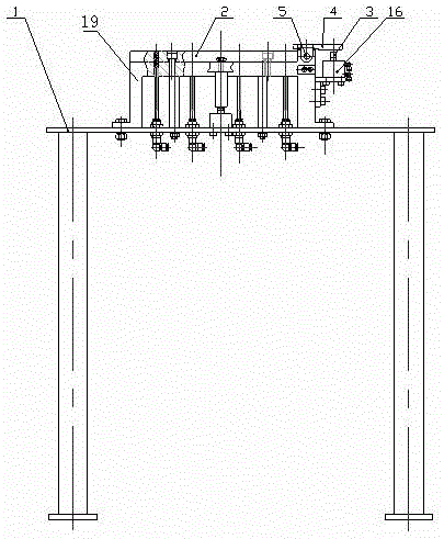
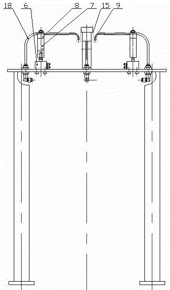
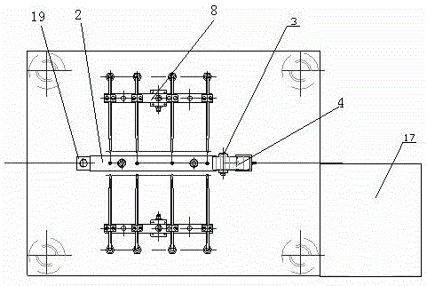
[0015] Such as Figure 1 to Figure 4 As shown, a fixed-point and quantitative refueling device for a car seat chute includes a workbench 1, a guide plate 2, a compression cylinder ejector 3, a compression plate 4, a pin shaft 5, a cylinder 6, a cylinder ejector 7, and an oil circuit Distribution strip 8, fixed-point nozzle 9, two-position five-way reversing valve A10, two-position five-way reversing valve B11, seat frame chute 15, compression cylinder 16, oil station 17, oil pipeline 18, tooling bracket 19.

[0016] Tooling bracket 19 is installed in the middle of workbench 1, and guide plate 2 is housed above tooling bracket 19, and one end of tooling bracket 19 is movably connected to compression plate 4 by bearing pin 5, and compression plate 4 is provided with the compression plate that is fixed on tooling bracket 19 sides below. Compression cylin...


PUM


Abstract

The invention relates to a fixed-point quantitative oil filling device for chutes of an automobile seat. A tool support is installed in the middle of a worktable and provided with a guide plate. One end of the tool support is movably connected with a pressing plate through a pin shaft. A pressing air cylinder fixed to the lateral side of the tool support is arranged below the pressing plate, and a pressing air cylinder ejector rod of the pressing air cylinder is connected with the pressing plate in a contact mode. Air cylinders are installed on the portions, on the two sides of the tool support, of the worktable, and air cylinder ejector rods of the air cylinders are fixedly connected with oil-way distribution bars. One end of each oil-way distribution bar is connected with a plurality of fixed-point spraying nozzles located on one side of the tool support, and the other end of each oil-way distribution bar is connected with a lubricating grease supply device through a plurality of oil-way pipelines. The fixed-point quantitative oil filling device solves the problem that lubricating grease quantitation can not be controlled in manual operation, guarantees that lubricating grease can be reliably injected into grooves of the symmetric chutes on the two sides of an automobile seat frame seat basin in a fixed-point quantitative mode, and is high in automation degree, convenient to operate and maintain, reliable in movement, simple in structure and capable of meeting national detection standard requirements.

Description

technical field [0001] The invention relates to a fixed-point quantitative refueling device for automobile assembly, in particular to a fixed-point grease filling device for filling the grooves of symmetrical chute grooves on both sides of the seat pan of the automobile seat frame before leaving the factory after the automobile seat frame is assembled. Quantitative refueling device. Background technique [0002] China has promulgated a series of standards for the production and use performance of car seats and product delivery. In order to meet the standards, enterprises have formulated corresponding requirements and indicators in the process of production and assembly of seats and before the products leave the factory. One of them is the requirements and indicators of the oil point and oil volume distribution of the grooves of the symmetrical chute on both sides under the seat frame pan before leaving the factory. It is required that the grooves on both sides of the symmet...

Claims


Application Information

Patent Timeline
Patent Type & Authority Patents(China)
IPC IPC(8): F16N7/38F16N27/00
Inventor 沈秀国陆保康王敏勇
Owner SHANGHAI INST OF TECH
Why Eureka
Try Eureka