Tube hole type distributing device

A material distributing device and tube hole technology, which is applied in the field of tube hole type material distributing device, can solve the problems of low equipment load, uneven material distribution, low processing efficiency, etc., and achieve the effect of simple structure, uniform mixing, and not easy to block

Active Publication Date: 2015-05-20
陈际平
View PDF4 Cites 0 Cited by
  • Summary
  • Abstract
  • Description
  • Claims
  • Application Information

AI Technical Summary

Problems solved by technology

[0003] In order to overcome the disadvantages of easy blockage, uneven distribution, low equipment load, and low processing efficiency in the existing distribution device, the present invention provides a tube hole type distribution device

Method used


Image

  • Tube hole type distributing device

Examples


Embodiment Construction

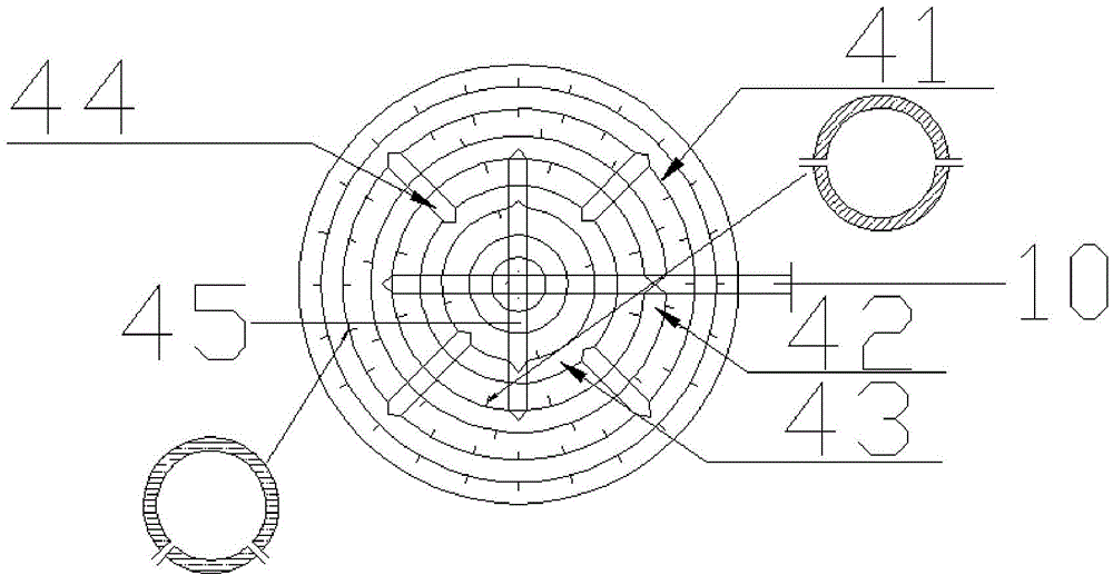
[0010] refer to figure 1 , a pipe-hole type distribution device, including a first ring pipe 43, a second ring pipe 42 and a third ring pipe 41 arranged coaxially, and the second ring pipe 42 is arranged along the axis line in the first ring pipe 43. Below the ring 43 pipe and the third ring pipe 41, the first ring pipe 43 is arranged inside the third ring pipe 41 to form a double-layer pipe, and the radius of the second ring pipe 42 is between that of the first ring pipe 42. Between the radius of the pipe 43 and the radius of the third ring pipe 41; the first ring pipe 43, the second ring pipe 42 and the third ring pipe 41 are all provided with distribution holes; the feeding pipe It is communicated with the first ring pipe 43 through the first communication pipe. The first communication pipe is the diameter orientation of the first ring pipe 43 and the feeding center pipe to form a T-shaped pipe, which is communicated with the first ring pipe 43. , the other end of the feed...


PUM


Abstract

The invention discloses a tube hole type distributing device which comprises a first ring tube, a second ring tube and a third ring tube coaxially arranged, wherein the second ring tube is arranged between the first and third ring tubes along the axis, the first ring tube is arranged inside the third ring tube to form a double-layer tube, and the radius of the second ring tube is set between the radius of the first ring tube and the radius of the second ring tube. The first, second and third ring tubes are provided with distributing holes. A feed tube is communicated with the first ring tube through a first communicated tube, the first communicated tube is a T-shaped tube formed with a feed central tube in diameter direction of the first ring tube and is communicated with the first ring tube, the other end of the feed tube is communicated with a feed reflowing and mixing tube, and a second communicated tube penetrates through the first ring tube in the pipe diameter direction. The device disclosed by the invention can distribute materials uniformly and ensures a sufficient contact area, so that the reaction efficiency is relatively high.

Description

technical field [0001] The present invention relates to a pipe hole type distributing device. Background technique [0002] The efficiency of anaerobic sludge bed treatment and the pros and cons of the effect, in which the uniformity of distribution has a great influence, only when the entire section of the feed passes through the area of ​​the sludge bed evenly, so that the feed liquid and the anaerobic granular sludge are fully mixed, can the high level be achieved. load and high efficiency. If the cloth is not uniform, it will cause some water flow to produce short flow and penetrate the sludge bed area, directly endangering the normal operation of the entire device, and the treatment effect will drop sharply. The existing distribution device has the disadvantages of easy blockage, uneven distribution, low equipment load and low processing efficiency. SUMMARY OF THE INVENTION [0003] In order to overcome the shortcomings of the existing distribution device, such as e...

Claims


Application Information

Patent Timeline
Patent Type & Authority Patents(China)
IPC IPC(8): C02F3/28
Inventor 陈际平
Owner 陈际平
Why Eureka
Try Eureka