
Flyback boosting circuit, LED (light emitting diode) backlight driving circuit and liquid crystal display

一种升压电路、反激式的技术,应用在电光源、静态指示器、电致发光光源等方向,能够解决限制输出电压范围等问题,达到降低发热量大、提高输出电压范围的效果

Active Publication Date: 2014-04-23
TCL CHINA STAR OPTOELECTRONICS TECH CO LTD
View PDF5 Cites 4 Cited by
  • Summary
  • Abstract
  • Description
  • Claims
  • Application Information

AI Technical Summary

Problems solved by technology

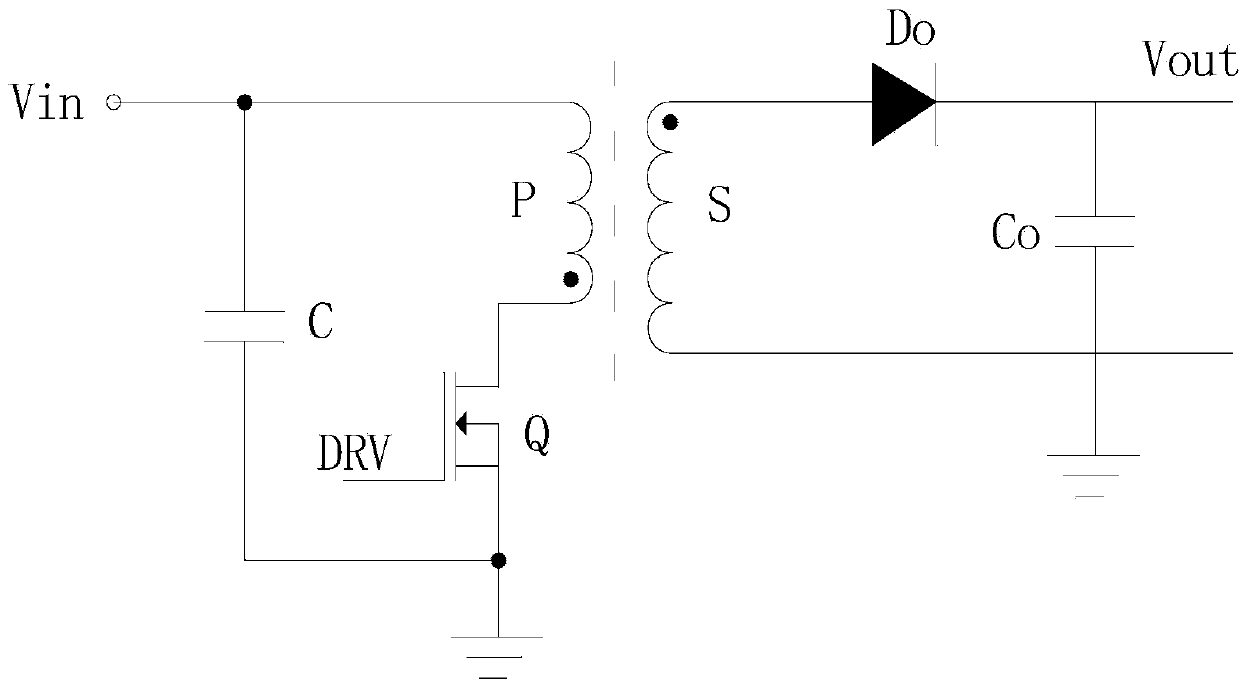
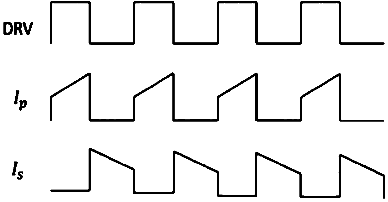
In the existing circuit, a single primary coil and a single switching element are used. When the value of D is designed to be greater than 50%, a large amount of heat will be generated during the opening process of the switching element. Therefore, the value of D is generally limited to less than 50%. limits the range of the output voltage Vout

Method used


Image

  • Flyback boosting circuit, LED (light emitting diode) backlight driving circuit and liquid crystal display
  • Flyback boosting circuit, LED (light emitting diode) backlight driving circuit and liquid crystal display
  • Flyback boosting circuit, LED (light emitting diode) backlight driving circuit and liquid crystal display

Examples


Embodiment Construction

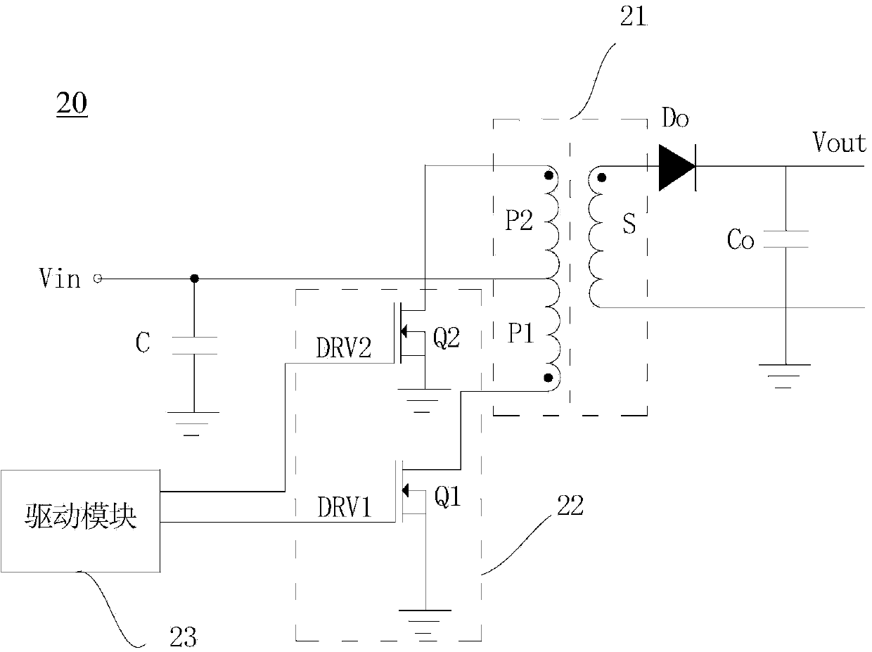
[0023] In order to solve the problems existing in the prior art, the idea of ​​the present invention is to use multiple primary coils in the transformer for energy conversion, and the multiple primary coils are controlled by multiple switching elements, so as to break through the existing duty cycle of a single switching element To limit the problem below 50%, increase the output voltage range.

[0024] Based on the above ideas, the technical solution provided by the present invention is a flyback boost circuit, including a transformer, a switch module, a drive module and an output diode, the transformer includes a primary coil and a secondary coil, and the secondary coil and the primary coil The turns ratio of the primary coil is K; the end of the same name of the primary coil is connected to the switch module, the switch module controls the conduction or disconnection of the primary coil, and the other end of the primary coil is connected to the input voltage; The drive modu...


PUM


Abstract

The invention discloses a flyback boosting circuit which comprises a transformer, a switch module, a driving module and an output diode, wherein the transformer is provided with n primary coils and a secondary coil; the switch module is provided with n switch elements; the dotted terminals of the n primary coils are respectively connected with the n switch elements in a one-to-one correspondence manner; the other end of each primary coil is connected with input voltage; the dotted terminal of the secondary coil is connected to the positive end of the output diode, and the other end of the secondary coil is grounded; an output capacitor is connected between the negative end of the output diode and the ground; the driving module supplies control signals to the n switch elements respectively to control the n switch elements to be sequentially switched on one by one within the time that the duty ratio is D; the sum of the duty ratios of the n switch elements is D, and n is an integer larger than or equal to 2. The invention also provides an LED (light emitting diode) backlight driving circuit comprising the flyback boosting circuit and a liquid crystal display comprising the backlight driving circuit.

Description

technical field [0001] The invention relates to a flyback boost circuit, an LED backlight drive circuit comprising the flyback boost circuit, and a liquid crystal display provided with the LED backlight drive circuit. Background technique [0002] With the continuous advancement of technology, the backlight technology of liquid crystal display devices has been continuously developed. Traditional liquid crystal display devices use cold cathode fluorescent lamps (CCFL) as backlight sources. However, due to the shortcomings of CCFL backlight such as poor color reproduction ability, low luminous efficiency, high discharge voltage, poor discharge characteristics at low temperature, and long time for heating to reach a stable gray level, the backlight technology using LED backlight has been developed; In the liquid crystal display device, the LED backlight is arranged opposite to the liquid crystal display panel, so that the LED backlight provides display light to the liquid crys...

Claims


Application Information

Patent Timeline
Patent Type & Authority Applications(China)
IPC IPC(8): G09G3/36G09G3/34H05B44/00
CPCH02M3/33569Y02B20/30H05B47/10H05B45/385G02F1/133603G09G3/3406H05B45/37G02F1/13306G02F1/133612H05B45/46G09G3/34
Inventor 王照曹丹
Owner TCL CHINA STAR OPTOELECTRONICS TECH CO LTD
Learn More