Traction apparatus of cross-country tractor

A traction device and tractor technology, applied in the field of off-road tractors, can solve the problems of unreasonable space layout, unreliable stability, limited bearing capacity, etc., and achieve the effect of compact structure, large bearing pressure and strong bearing capacity

Inactive Publication Date: 2014-04-23
湖南长沙果福车业有限公司
View PDF6 Cites 1 Cited by
  • Summary
  • Abstract
  • Description
  • Claims
  • Application Information

AI Technical Summary

Problems solved by technology

[0002] Existing farmland operating machines are mainly bent-over steering, and long-term use shows that its defects are: the side of the traction box in direct contact with the traction shaft is easy to wear, the main pin is easy to wear and deform, and the bearing capacity is small and easy to change.
[0003] CN103202120A disclosed on July 17, 2013 a traction device for a multi-purpose farmland working machine, which is provided with a plane bearing at the lower end surface of the traction box in direct contact with the traction shaft, and a copper sleeve is provided on the traction kingpin. Although the device It can reduce the deformation of the kingpin, the wear of the kingpin and the wear of the traction box to a certain extent, but it is still not ideal. In addition, the space layout of the device is not reasonable enough, the bearing capacity it bears is limited, and the stability needs to be improved

Method used


Image

  • Traction apparatus of cross-country tractor
  • Traction apparatus of cross-country tractor

Examples


Embodiment Construction

[0016] The present invention will be further described below in conjunction with the accompanying drawings and embodiments.

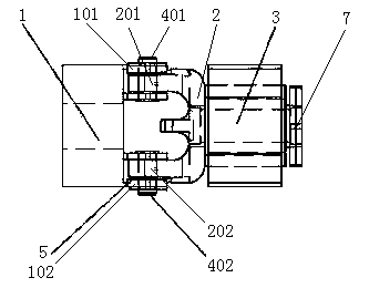
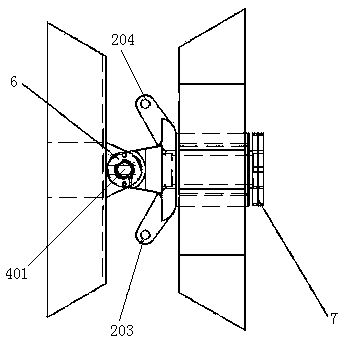
[0017] Referring to the accompanying drawings, this embodiment includes a traction box 1, a traction shaft 2, a traction shaft fixing box 3, a first traction kingpin 401, a second traction kingpin 402, a wear-resistant flat pad 5, a lock plate 6 and a traction shaft fixing nut 7. The traction box 1 is welded on the left and right longitudinal beams of the front frame. A pair of connectors I101 are provided on the upper rear end of the traction box 1, and a pair of connectors II102 are provided on the lower part. The connectors I101, connectors II102 is respectively provided with a kingpin mounting hole, and the middle of the traction box 1 is provided with a square hole for installing the rear drive shaft; the traction shaft fixing box 3 is welded on the left and right longitudinal beams of the rear frame, and the traction shaft 2 is equipped with a sha...


PUM


Abstract

The invention provides a traction apparatus of a cross-country tractor. The traction apparatus comprises a traction box, a traction shaft, a traction shaft fixing box, a first traction main pin, a second traction main pin, a wearproof flat gasket, a locking plate and a traction shaft fixing nut, wherein a pair of connectors I is arranged at the upper part of the rear end of the traction box, while a pair of connectors II is arranged at the lower part of the same; a shaft sleeve is mounted on the traction shaft; the traction shaft is mounted in the traction shaft fixing box and fastened by the traction shaft fixing nut; the traction shaft is a hollow shaft; an upper connecting lug, a lower connecting lug, a left connecting lug and a right connecting lug are arranged at the front end of the traction shaft; the upper connecting lug is connected with the connector I through the first traction main pin; the lower connecting lug is connected with the connector II through the second traction main pin; grooves are formed on both upper and lower ends of the first traction main pin and the second traction main pin; the first traction main pin and the second traction main pin both both are locked by the opening of the locking plate; the wearproof flat gasket is mounted at the lower end face of the traction shaft in contact with the traction box. The traction apparatus of the cross-country tractor is capable of reducing the deformation of the main pins, the abrasion of the main pins and the abrasion of the traction box, rational in spatial arrangement, high in carrying capacity and high in stability.

Description

technical field [0001] The invention relates to an off-road tractor, in particular to a traction device for an off-road tractor. Background technique [0002] Existing farmland work machines are mainly bent-over steering. Long-term use shows that the defects are: the side of the traction box in direct contact with the traction shaft is easy to wear, the kingpin is easy to wear and deform, and the bearing capacity is small and easy to change. [0003] CN103202120A disclosed on July 17, 2013 a traction device for a multi-purpose farmland working machine, which is provided with a plane bearing at the lower end surface of the traction box in direct contact with the traction shaft, and a copper sleeve is provided on the traction kingpin. Although the device It can reduce kingpin deformation, kingpin wear and traction box wear to a certain extent, but it is still not ideal. In addition, the space layout of the device is not reasonable enough, the bearing capacity it bears is limit...

Claims


Application Information

Patent Timeline
Patent Type & Authority Applications(China)
IPC IPC(8): B60D1/14A01B59/04
Inventor 粟丰韦信锐刘闯黄岳陈力周盛现雷再福卢本良龙傲奇黄谊蒋志广涂宏辉汪金秀陈坤蒋新武汪建灿李勇
Owner 湖南长沙果福车业有限公司
Why Eureka
Try Eureka